Applications / Medical Devices
MRI-compatible actuation: piezo as the answer to the magnetic constraint
Why ferromagnetic-free piezoelectric motors are the dominant actuator choice inside the MRI bore
Magnetic resonance imaging operates by immersing the patient in a powerful static magnetic field, applying precisely timed radiofrequency (RF) pulses, and detecting the faint RF signals emitted by hydrogen nuclei as they relax. The imaging process depends on field homogeneity measured in parts per million and signal levels measured in microvolts. Introducing any ferromagnetic material or any source of electromagnetic interference into the scanner bore can distort the magnetic field, inject noise into the receiver chain, and render the resulting images clinically useless.
This constraint makes conventional electromagnetic motors, which contain permanent magnets, ferromagnetic stator cores, and commutated windings, fundamentally incompatible with the MRI environment (see EMI and magnetic field considerations for a broader comparison). Piezoelectric ultrasonic motors, built from non-magnetic ceramics, phosphor bronze, and aluminum, can operate inside the bore without disturbing the imaging process. This article examines the MRI compatibility requirements in quantitative detail, explains why piezo motors satisfy them, discusses the remaining engineering challenges, and surveys the current state of MRI-compatible piezo-actuated systems. For a broader comparison of when piezo is the right choice, see when NOT to use piezo.
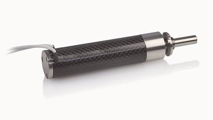
Image: Physik Instrumente (PI)
The MRI environment
Static magnetic field (B0)
Clinical MRI scanners operate at static field strengths of 1.5 T, 3 T, and (increasingly) 7 T. Research systems reach 11.7 T and beyond. For context, the Earth's magnetic field is approximately 50 uT; a 3 T scanner's field is 60,000 times stronger.
The B0 field extends beyond the bore in a fringe field that decreases with distance. The 5 gauss (0.5 mT) line, which is the safety boundary for ferromagnetic objects, typically lies 3 to 5 m from the bore center for an unshielded 3 T magnet and 1.5 to 2.5 m for an actively shielded magnet.
Any ferromagnetic object within the bore experiences a translational force proportional to the product of its magnetic susceptibility, volume, and the spatial gradient of B^2. This force can be enormous: a small steel wrench in a 3 T scanner experiences a pull of tens of newtons, enough to become a lethal projectile. Even weakly ferromagnetic materials (some stainless steels, nickel-based alloys) experience forces that can shift precision mechanisms out of alignment.
Gradient fields
Spatial encoding in MRI requires magnetic field gradients, generated by resistive gradient coils inside the bore. These gradients switch rapidly (slew rates of 100 to 200 T/m/s) and produce time-varying magnetic fields that induce eddy currents in any conductive material within the bore. Eddy currents in conductive loops or sheets produce two effects:
- Heating: Joule heating from induced currents. For a 10 cm diameter copper loop in a 3 T scanner with 150 T/m/s gradients, the induced power can reach several watts, enough to cause burns.
- Field distortion: The eddy current's own magnetic field opposes the applied gradient, distorting the spatial encoding and causing image artifacts (ghosting, geometric distortion).
RF excitation field (B1)
The RF transmit coil produces a rotating magnetic field at the Larmor frequency (63.9 MHz at 1.5 T, 127.7 MHz at 3 T, 297.2 MHz at 7 T). Peak B1 field strength is typically 10 to 30 uT, with RF power of 1 to 20 kW (pulsed). Any conductive structure in the bore can act as an antenna, absorbing RF energy (causing heating) or re-radiating it (causing image artifacts).
RF receive sensitivity
The MRI receiver detects nuclear magnetic resonance signals with amplitudes on the order of microvolts. The signal-to-noise ratio (SNR) determines image quality and is proportional to B0^(7/4) for a given voxel size and imaging time. Any electromagnetic emission within the receiver bandwidth (the Larmor frequency +/- a few hundred kHz) directly degrades SNR.
Why conventional motors fail in MRI
Permanent magnet motors
Brushless DC motors and brushed DC motors contain permanent magnets (NdFeB or ferrite) in the rotor. These experience:
- Saturation: The permanent magnets saturate in the B0 field, eliminating the internal field gradient that produces motor torque. The motor simply stops working.
- Projectile risk: NdFeB magnets are strongly ferromagnetic. Even a small motor magnet (a few grams) experiences forces of tens of newtons in the bore fringe field.
- Field distortion: The magnet's own field and the susceptibility-induced field distortion extend several centimeters, distorting B0 homogeneity in the imaging region.
Stepper motors
Stepper motors contain ferromagnetic stator laminations and (usually) a permanent magnet rotor. They share all the problems of permanent magnet motors, plus:
- EMI from drive signals: Stepper motors are driven by switched current waveforms with significant harmonic content. These harmonics can fall within the MRI receiver bandwidth and inject noise directly into the image.
Voice coil actuators
Linear voice coil actuators (moving-coil or moving-magnet) can be designed with non-ferromagnetic materials, but the interaction between the actuator's current-carrying conductors and the scanner's B0 field produces parasitic Lorentz forces that depend on orientation and position within the bore. These forces are unpredictable and position-dependent, making precision motion control difficult. Additionally, the high B0 field produces large back-EMF in the moving coil, requiring the drive electronics to overcome this voltage.
Pneumatic and hydraulic actuators
Pneumatic and hydraulic systems avoid electromagnetic issues entirely and have been used in MRI-compatible robots. However, they introduce their own challenges: compressibility (for pneumatics), bulk, slow response, limited precision, and difficulty achieving fine position control. They are used where the motion requirements are simple (extend/retract) but are poorly suited to multi-axis precision positioning.
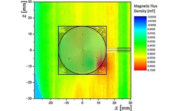
Image: Physik Instrumente (PI)
Why piezoelectric motors work in MRI
Material composition
A typical traveling-wave ultrasonic motor consists of:
-
Piezoceramic elements: Lead zirconate titanate (PZT). Diamagnetic, with volume magnetic susceptibility of approximately -15 x 10^-6 (SI). For comparison, water is -9 x 10^-6 and human tissue ranges from -7 to -11 x 10^-6. The susceptibility mismatch between PZT and tissue is small and produces negligible field distortion at clinical imaging distances (>5 cm).
-
Stator body: Typically phosphor bronze (Cu-Sn-P alloy). Paramagnetic, with susceptibility of approximately +7 x 10^-6. Non-ferromagnetic. Good electrical conductivity, which means gradient-induced eddy currents must be considered (discussed below).
-
Rotor: Typically aluminum alloy (Al 7075 or 6061). Paramagnetic, susceptibility approximately +21 x 10^-6. Non-ferromagnetic. Highly conductive.
-
Friction lining: Alumina ceramic (Al2O3) or polymer composite. Negligible susceptibility.
-
Output shaft bearing: Can use ceramic ball bearings (Si3N4 balls, PEEK or ceramic races) to eliminate all ferromagnetic content. Standard steel bearings must be replaced.
-
Spring/preload mechanism: Beryllium copper or titanium springs replace steel springs.
None of these materials is ferromagnetic. The motor produces no static magnetic field and experiences negligible force or torque in the B0 field.
Electromagnetic emission profile
The motor's drive signals operate at ultrasonic frequencies, typically 30 to 80 kHz. The Larmor frequencies for clinical MRI are:
| Field strength | Larmor frequency |
|---|---|
| 1.5 T | 63.9 MHz |
| 3 T | 127.7 MHz |
| 7 T | 297.2 MHz |
The fundamental drive frequency and its harmonics are separated from the Larmor frequency by three to four orders of magnitude. Even the 1,000th harmonic of a 40 kHz drive signal (40 MHz) is below the 1.5 T Larmor frequency. This spectral separation is a powerful advantage: the motor's electromagnetic emissions, while non-zero, fall entirely outside the MRI receiver bandwidth and therefore do not inject noise into the image.
However, two emission mechanisms can still cause problems:
-
Broadband noise from switching electronics: If the motor driver uses PWM or class-D amplification, the switching transients can contain spectral energy at RF frequencies. Proper filtering and shielding of the driver electronics is essential. Best practice is to place the driver electronics outside the RF-shielded room (the Faraday cage) and route only the low-frequency drive signals through filtered penetration panels.
-
Conducted emissions on cables: The cables connecting the motor to the driver can act as antennas, radiating electromagnetic energy at the drive frequency and its harmonics. Common-mode chokes and shielded cables, terminated at the penetration panel, mitigate this.
Quantitative SNR impact
Published studies have measured the SNR impact of operating piezoelectric motors inside the MRI bore. Representative results:
| Study / system | Scanner | Motor type | Distance from isocenter | SNR change |
|---|---|---|---|---|
| Chinzei et al. (2000) | 0.5 T open | USR60 traveling wave | 15 cm | less than 1% degradation |
| Fischer et al. (2008) | 3 T closed bore | Shinsei USR30 | 10 cm | less than 2% degradation |
| Su et al. (2015) | 3 T closed bore | Piezo LEGS linear | 5 cm | 3 to 5% degradation |
| Sengupta et al. (2020) | 7 T research | Custom piezo rotary | 8 cm | 2 to 4% degradation |
For clinical MRI, an SNR degradation of less than 5% is generally considered acceptable and is within the noise floor of patient-to-patient variability. At 3 T and 7 T, SNR is sufficiently high that a 2 to 5% reduction does not affect diagnostic quality for most applications.
The key finding across these studies is that the SNR impact depends strongly on the quality of the RF shielding and filtering. A well-shielded system with the driver electronics outside the scanner room and proper cable filtering achieves less than 2% SNR degradation even at close range. A poorly shielded system can cause 10 to 20% degradation or visible artifacts.
MRI-compatible materials selection
Designing a complete MRI-compatible actuator assembly (not just the motor, but the entire mechanism including bearings, encoders, structural components, and cabling) requires careful material selection. The following table summarizes common material choices:
| Component | Standard material | MRI-compatible substitute | Notes |
|---|---|---|---|
| Motor stator | Phosphor bronze (OK) | No change needed | Already non-ferromagnetic |
| Motor PZT | PZT-4/PZT-8 (OK) | No change needed | Diamagnetic |
| Bearings | Steel (52100) | Si3N4 ceramic / PEEK | Critical substitution; steel bearings are ferromagnetic |
| Shaft | Steel (440C) | Titanium (Ti-6Al-4V) or ceramic | Paramagnetic, excellent strength |
| Springs | Steel music wire | BeCu or Elgiloy | Both non-ferromagnetic |
| Fasteners | Steel (A2 stainless) | Titanium or brass or PEEK | A2/A4 stainless is acceptable if tested; some grades are weakly ferromagnetic |
| Encoder | Optical with steel shaft | Optical with Ti shaft, or capacitive | Magnetic encoders are prohibited |
| Cables | Standard PVC-insulated | Non-ferromagnetic shielded, filtered at penetration | Cable shielding is critical |
| Housing | Aluminum (OK) | No change needed, or use PEEK for imaging proximity | Aluminum eddy currents may require attention |
The stainless steel trap
A common and dangerous mistake is assuming that "stainless steel" is non-magnetic. Austenitic stainless steels (304, 316) are nominally non-ferromagnetic, but cold working (machining, bending, swaging) can induce a martensitic phase transformation that makes them weakly ferromagnetic. A 316L stainless steel screw that was perfectly safe before machining may become detectably magnetic after threading. Every metallic component intended for use inside the MRI bore should be tested with a handheld gaussmeter or by the deflection test specified in ASTM F2052.
Eddy current considerations
Even non-ferromagnetic conductors interact with the MRI gradient fields. When the gradient coils switch (which happens thousands of times per second during fast imaging sequences like echo-planar imaging, or EPI), changing magnetic flux through any conductive loop induces eddy currents. For a solid aluminum rotor 30 mm in diameter in a 3 T scanner with 40 mT/m gradients and 150 T/m/s slew rate:
Induced EMF ~ (pi x r^2) x (dB/dt) = pi x (0.015)^2 x 150 = 0.106 V
The resulting eddy current depends on the conductor's resistance and geometry. For a continuous ring of aluminum, the current can be significant (hundreds of milliamps), producing heating and field distortion.
Mitigation strategies:
- Segmented conductors: Break continuous conductive loops with insulating gaps. A segmented rotor or stator reduces eddy current magnitude proportionally to the number of segments.
- Smaller components: Eddy current magnitude scales with the square of the conductor's radius. Smaller motors produce proportionally less eddy current distortion.
- Distance from isocenter: Eddy current effects diminish with distance from the gradient isocenter. Placing the motor 10 to 20 cm from the imaging plane significantly reduces artifacts.
- Non-conductive materials: Using PEEK or ceramic structural components instead of aluminum eliminates eddy currents in those parts entirely.
Existing MRI-compatible piezo systems
Surgical and interventional robots
The most mature application of MRI-compatible piezo motors is in surgical and interventional robots that operate inside the bore during imaging. These systems enable real-time MRI-guided procedures:
Prostate biopsy robots: Multiple groups (Johns Hopkins, Worcester Polytechnic Institute, Brigham and Women's Hospital) have developed MRI-compatible robots using piezo motors for needle guidance. These typically use 2 to 4 traveling-wave rotary motors driving ball screws or cable transmissions to position a needle guide with 1 to 2 mm accuracy. The robot operates inside the 3 T bore with the patient, and MRI images are acquired during the procedure to guide needle placement.
Neurosurgical robots: MRI-compatible stereotactic robots use piezo motors to position surgical tools (biopsy needles, electrode arrays, laser fibers) within the brain during intraoperative MRI. Accuracy requirements are extreme (sub-millimeter), and the motor's zero-backlash, high-resolution capability is essential.
Breast biopsy: MRI-guided breast biopsy systems use piezo motors to position the biopsy needle within suspicious lesions visible only on MRI. The system must operate inside the bore without degrading image quality.
Functional MRI (fMRI) stimulus devices
Functional MRI studies require delivering controlled stimuli (tactile, haptic, visual, auditory) to subjects inside the scanner. Piezo-actuated devices provide:
- Tactile stimulators: Piezo linear motors drive probes that apply controlled forces to the subject's skin. The motor's non-magnetic nature ensures no interference with the BOLD signal being measured.
- Haptic interfaces: Force-feedback devices for studying sensorimotor control during fMRI. The motor must be transparent to the imaging process while providing forces of 1 to 10 N at the fingertip.
- Motion platforms: Subject positioning systems that move the head or limb during scanning to study vestibular processing or motion correction.
Focused ultrasound therapy
MRI-guided focused ultrasound (MRgFUS) uses high-intensity focused ultrasound to ablate tissue (tumors, uterine fibroids, brain lesions) while MRI monitors the temperature in real time. The ultrasound transducer array must be mechanically positioned within the bore. Piezo motors drive the positioning mechanisms for these systems, with commercial implementations by Insightec (Exablate) and others.
Performance characteristics of MRI-compatible piezo motors
The MRI compatibility modifications (ceramic bearings, titanium shafts, non-magnetic springs) generally have minimal impact on motor performance:
| Parameter | Standard motor | MRI-compatible version | Change |
|---|---|---|---|
| Continuous torque | 0.1 Nm | 0.09 to 0.1 Nm | 0 to 10% reduction |
| No-load speed | 150 RPM | 140 to 150 RPM | 0 to 7% reduction |
| Holding torque | 0.3 Nm | 0.25 to 0.3 Nm | 0 to 17% reduction |
| Life | 5,000 h | 3,000 to 5,000 h | 0 to 40% reduction |
| Mass | 30 g | 28 to 35 g | -7 to +17% |
The largest performance change comes from the bearing substitution: ceramic bearings have slightly different friction characteristics than steel bearings, and PEEK races have lower stiffness than steel races. The holding torque reduction (up to 17%) occurs because the bearing friction contributes to the overall holding capability, and ceramic-on-PEEK friction is lower than steel-on-steel.
Life reduction, when it occurs, is typically due to the ceramic bearing races being less tolerant of shock loading than hardened steel races. For the low-speed, precision applications typical of MRI robots, this is rarely a practical concern.
Design guidelines for MRI-compatible piezo actuator systems
Electronics placement
The single most important design decision is where to place the motor driver electronics. Three options exist:
-
Outside the scanner room: The driver is placed in the equipment room behind the penetration panel. Only the motor drive cables pass through the filtered wall penetration. This provides the best RF isolation and is the preferred approach. Cable length is typically 3 to 5 m, which can cause signal attenuation at the drive frequency; this is compensated by increasing the driver output voltage.
-
Inside the scanner room, outside the bore: The driver is mounted on the scanner table or on the wall, typically at the 5 gauss line. This reduces cable length but requires RF shielding of the driver enclosure.
-
Inside the bore: The driver is integrated with the motor mechanism, minimizing cable length. This is the most challenging approach and requires extensive shielding, non-magnetic components in the driver, and careful EMI management. It is sometimes necessary for very compact robotic systems.
Cable management
Cables inside the bore must be:
- Shielded: Braided copper or aluminum shields, connected to the penetration panel ground
- Filtered: Common-mode chokes at both ends of the cable
- Routed carefully: Avoid forming loops that couple to gradient fields; route cables along the bore axis (parallel to B0) to minimize gradient interaction
- Length-controlled: Cable lengths that are resonant at the Larmor frequency (multiples of lambda/2, where lambda is the RF wavelength in the cable) can act as efficient antennas; avoid these lengths or add series impedances to detune them
Safety considerations
The ASTM F2503 standard defines MRI safety labeling. A complete piezo actuator system inside the bore should be tested and labeled according to this standard:
- MR Safe: Contains no metallic components and poses no hazard in all MRI environments. Difficult to achieve for a motor (which contains metallic components).
- MR Conditional: Safe under specified conditions (field strength, SAR limits, gradient slew rate, spatial gradient). Most piezo motor systems will be MR Conditional.
- MR Unsafe: Contains ferromagnetic components. This must never be the case for a motor intended for bore use.
Testing per ASTM F2052 (displacement force), F2213 (torque), F2182 (RF heating), and F2119 (artifact assessment) is required for regulatory approval of the complete system.
RF heating assessment
Although piezo motors do not generate RF themselves, conductive components inside the bore can absorb RF energy from the scanner's transmit coil, causing localized heating. The specific absorption rate (SAR) limits defined by IEC 60601-2-33 apply to the patient; any additional heating from the actuator mechanism must not cause the local SAR to exceed these limits.
RF heating is highly geometry-dependent. Long, thin conductors aligned with the RF electric field experience the most heating. Short, wide conductors experience less. Dedicated RF heating tests (per ASTM F2182) using gel phantoms and fiber-optic temperature sensors are the standard method for quantifying this risk.
For a typical piezo motor (30 mm diameter, 10 mm long), the RF heating contribution is small: temperature rises of less than 0.5 C in the gel phantom adjacent to the motor have been reported at 3 T with standard clinical sequences (SAR of 2 W/kg). This is well within acceptable limits.
Field strength considerations: 1.5 T, 3 T, and 7 T
1.5 T
At 1.5 T, MRI compatibility is relatively straightforward. The force on weakly paramagnetic materials is low, gradient slew rates are moderate, and the Larmor frequency (63.9 MHz) is well separated from the motor drive frequency. Most properly designed piezo motor systems work at 1.5 T with minimal modifications beyond replacing ferromagnetic components.
3 T
At 3 T, all magnetic forces and eddy current effects double compared to 1.5 T (forces scale as B x dB/dx, and gradients are similar or stronger). The Larmor frequency doubles to 127.7 MHz, meaning cables that were safe at 1.5 T may become resonant antennas at 3 T. More careful cable management and filtering is required. RF heating also increases due to higher SAR at 3 T.
7 T
At 7 T, the challenges intensify significantly:
- Susceptibility artifacts: Even small susceptibility differences between motor materials and tissue create visible artifacts extending several centimeters from the motor at 7 T. This may preclude placing the motor close to the imaging region.
- RF wavelength shortening: At 297 MHz, the RF wavelength in tissue is approximately 12 cm. RF field homogeneity degrades, and localized SAR hotspots become more common. Any conductive structure near the patient can concentrate RF energy.
- Eddy currents: Higher gradient performance in 7 T scanners (slew rates up to 200 T/m/s) increases eddy current effects.
- Force on paramagnetic materials: The translational force on paramagnetic components scales with B x dB/dx. At 7 T, even aluminum and titanium components can experience measurable (though still small) forces. These forces are orders of magnitude below the motor's holding torque and are not a safety concern, but they may need to be accounted for in high-precision positioning applications.
Despite these challenges, multiple research groups have successfully operated piezo motors inside 7 T scanners for neuroscience and interventional applications.
Conclusion
Piezoelectric ultrasonic motors are the actuator technology of choice for MRI-compatible systems, a position they have held for over two decades with no serious competitor. Their non-ferromagnetic construction eliminates projectile risk and field distortion. Their ultrasonic operating frequency is separated from the MRI receive band by three to four orders of magnitude, ensuring negligible SNR impact when properly shielded. The engineering challenges that remain (eddy currents, cable management, RF heating assessment) are well understood and manageable with established design practices.
For system designers entering this space, the critical takeaway is that MRI compatibility is a system-level property, not just a motor property. A perfectly non-magnetic motor connected to the wrong cable, driven by an unshielded driver, or assembled with a single ferromagnetic screw will fail catastrophically in the MRI environment. Every component, every cable, every fastener must be evaluated. Piezo motors make this achievable because they start from a non-magnetic baseline; the designer's job is to maintain that baseline through the entire signal chain and mechanical assembly, not to fight against the fundamental physics of the actuator itself.