Applications / Optics & Photonics
Beam steering with piezo: bandwidth, resolution, and mechanical coupling
How piezoelectric tip-tilt actuators compare with galvo mirrors for precision beam steering, and the mechanical design tradeoffs that determine system performance
Beam Steering with Piezo: Bandwidth, Resolution, and Mechanical Coupling
Precision beam steering is a core capability in laser machining, free-space optical communications, lidar, adaptive optics, and optical testing. The actuator that tilts the steering mirror determines the system's angular resolution, bandwidth, and dynamic range. Galvanometer (galvo) mirrors have dominated beam steering for decades, but piezoelectric tip-tilt actuators offer fundamentally different performance characteristics that make them the superior choice for applications demanding high resolution, high bandwidth, or both.
This article examines piezo-driven beam steering from first principles: the conversion of linear piezo displacement to angular motion, the bandwidth limits imposed by mirror mass and mount resonance, the resolution advantages over electromagnetic galvos, and the mechanical coupling effects that can degrade performance if not properly managed.
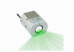
Image: Physik Instrumente (PI)
Angular Motion from Linear Actuators
Piezoelectric actuators produce linear displacement. Converting this to angular (tip-tilt) motion requires a mechanical transformation. Two primary approaches are used.
Lever-Arm Tip-Tilt
The simplest approach places a piezo stack actuator at a distance r from a pivot point. The actuator pushes against the back of the mirror mount, tilting it around the pivot. The angular displacement is:
theta = d / r
where d is the piezo linear displacement and r is the lever arm (distance from the actuator to the pivot).
For a piezo stack with 15 micrometers of travel and a 30 mm lever arm:
theta = 15 / 30000 = 0.5 milliradians = 500 microradians
This produces a beam deflection of 2 * theta = 1 milliradian (for a flat mirror; the factor of 2 arises because the reflected beam angle changes by twice the mirror tilt angle).
The angular resolution is:
delta_theta = delta_d / r
For a piezo with 0.1 nm resolution:
delta_theta = 0.1 / 30000 = 3.3 nanoradians
This 3.3 nanoradian resolution is far beyond what galvo mirrors can achieve (typically 1 to 10 microradians).
A two-axis tip-tilt stage uses two such actuator-lever pairs, oriented orthogonally. The pivot can be a single flexure (ball-and-socket or cross-blade flexure) or a pair of flexure hinges arranged in a gimbal configuration.
Segmented Actuator Approach
Instead of a single actuator and lever, three piezo actuators are arranged in a triangular pattern under a flat mirror. By driving the actuators differentially, tip and tilt are achieved. Piston (Z translation) is achieved by driving all three actuators equally.
For three actuators at radius R from the mirror center:
theta_x = (d_A - (d_B + d_C) / 2) / (R * sqrt(3) / 2) theta_y = (d_B - d_C) / R
The resolution and range calculations are similar to the lever-arm approach, with the actuator spacing R replacing the lever arm r.
The segmented approach has higher stiffness (three actuators share the load) and provides piston control as a bonus. The disadvantage is more complex drive electronics (three amplifier channels instead of two) and the need for precise actuator matching to avoid cross-coupling between tip, tilt, and piston.
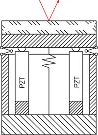
Image: Physik Instrumente (PI)
Bandwidth Requirements for Beam Stabilization
The required bandwidth for beam steering depends on the application. Low-bandwidth pointing applications (telescope guiding, alignment) need 1 to 100 Hz. High-bandwidth stabilization (vibration rejection, adaptive optics) needs 100 Hz to 10 kHz. Ultra-fast scanning (confocal microscopy, lidar) needs 1 to 100 kHz.
Vibration Rejection
In many beam steering applications, the primary function is to reject vibrations that disturb the beam pointing. The vibration spectrum determines the required bandwidth.
For a mirror on an optical bench subject to floor vibration, the tilt disturbance spectrum typically falls off as 1/f^2 above the bench's resonance frequency (1 to 10 Hz). The dominant tilt disturbance frequencies are 1 to 100 Hz, with amplitudes of 1 to 100 microradians depending on the bench and environment.
To reject these disturbances by 40 dB (100x), the tip-tilt servo bandwidth must exceed the disturbance frequency by a factor of 10 (for a simple integrator) or sqrt(100) = 10 (for a second-order servo). For a 100 Hz disturbance, this requires a 300 Hz to 1 kHz bandwidth, depending on the servo design.
Adaptive Optics
Atmospheric turbulence creates wavefront distortions with a temporal power spectrum described by the Greenwood frequency:
f_G = 0.43 * v_wind / r0
where v_wind is the wind velocity and r0 is the Fried parameter (a measure of atmospheric coherence length).
For v_wind = 10 m/s and r0 = 10 cm (typical for ground-based astronomy at visible wavelengths):
f_G = 0.43 * 10 / 0.1 = 43 Hz
The tip-tilt correction bandwidth must exceed f_G by a factor of 3 to 10 for effective correction, requiring 130 to 430 Hz bandwidth. For more turbulent conditions (v_wind = 30 m/s, r0 = 5 cm), f_G = 258 Hz, requiring bandwidths of 800 Hz to 2.6 kHz.
These bandwidth requirements are well within the capability of piezo tip-tilt stages but push the limits of galvo mirrors when combined with large mirror apertures.
Scanning Applications
For beam scanning (lidar, confocal microscopy), the bandwidth requirement is set by the scan rate and the desired angular resolution. A lidar scanner covering a 30-degree field of view at 10 Hz frame rate with 0.01-degree angular resolution needs:
Angular velocity: 30 degrees / (0.05 seconds per half-scan) = 600 degrees/s = 10.5 rad/s Points per scan: 30 / 0.01 = 3000 Point rate: 3000 * 10 = 30,000 points/s
The bandwidth for triangle-wave scanning at 10 Hz with 3000 points per scan requires harmonics up to approximately the 50th harmonic of the scan frequency, or 500 Hz. For sinusoidal scanning, the bandwidth equals the scan frequency (10 Hz), but the angular velocity varies across the scan, producing non-uniform point spacing.
Mechanical Resonance of Mirror Mounts
The achievable bandwidth of a piezo tip-tilt system is limited by the first mechanical resonance of the mirror mount. This resonance depends on the mirror mass, the mount stiffness, and the actuator stiffness.
Mirror Inertia
For a circular mirror of diameter D, thickness t, and density rho, the moment of inertia about a diameter axis is:
J = (pi / 64) * D^4 * t * rho
For a 25 mm diameter, 6 mm thick fused silica mirror (rho = 2200 kg/m^3):
J = (pi / 64) * (0.025)^4 * 0.006 * 2200 = 1.97 * 10^-8 kg*m^2
Mount Resonance
The torsional resonance frequency of the mirror on its mount is:
f_res = (1 / (2 * pi)) * sqrt(k_theta / J)
where k_theta is the torsional stiffness of the mount (in N*m/rad).
For a piezo actuator with stiffness k_linear = 100 N/micrometer at a lever arm of 15 mm:
k_theta = k_linear * r^2 = 100 * 10^6 * (0.015)^2 = 22,500 N*m/rad
f_res = (1 / (2 * pi)) * sqrt(22500 / 1.97 * 10^-8) = (1 / (2 * pi)) * sqrt(1.14 * 10^12) = 170 kHz
This is extremely high, which is one reason why small piezo tip-tilt mirrors achieve bandwidths of 10 to 50 kHz. The resonant frequency decreases with mirror size:
For a 100 mm diameter, 15 mm thick mirror:
J = (pi / 64) * (0.1)^4 * 0.015 * 2200 = 1.62 * 10^-5 kg*m^2 f_res = (1 / (2 * pi)) * sqrt(22500 / 1.62 * 10^-5) = 5.9 kHz
And for a 250 mm diameter, 40 mm thick mirror:
J = (pi / 64) * (0.25)^4 * 0.04 * 2200 = 1.06 * 10^-2 kg*m^2 f_res = (1 / (2 * pi)) * sqrt(22500 / 1.06 * 10^-2) = 232 Hz
The bandwidth scales inversely with mirror size. This is why large-aperture adaptive optics systems (with 200+ mm mirrors) have bandwidths of only 100 to 300 Hz, while small steering mirrors (10 to 25 mm) achieve bandwidths of 5 to 50 kHz.
Parasitic Resonances
The first torsional resonance of the mirror on the actuator is rarely the limiting factor. Parasitic resonances from the mirror's internal bending modes, the mount's structural modes, and the actuator's longitudinal resonance typically occur at lower frequencies and can couple into the tip-tilt response.
The mirror's first bending mode frequency for a circular plate is approximately:
f_bend = 0.469 * (t / D^2) * sqrt(E / (rho * (1 - nu^2)))
For a 50 mm diameter, 8 mm thick fused silica mirror (E = 72 GPa, nu = 0.17):
f_bend = 0.469 * (0.008 / 0.0025) * sqrt(72 * 10^9 / (2200 * (1 - 0.029))) = 0.469 * 3.2 * 5735 = 8.6 kHz
If the torsional mount resonance is 20 kHz but the mirror bending mode is at 8.6 kHz, the usable bandwidth is limited by the bending mode. The mirror must be thick enough (or made from a stiffer material) to keep the bending mode above the torsional resonance.
Material selection for mirrors: Silicon carbide (SiC) has a stiffness-to-density ratio 4x higher than fused silica, pushing the bending mode frequency 2x higher for the same dimensions. Beryllium is even better (6x stiffness-to-density ratio) but is rarely used for mirrors due to cost and polishing difficulty. For most high-performance applications, fused silica or Zerodur (for thermal stability) is used with adequate thickness.
Comparison with Galvo Mirrors
Galvanometer scanners use an electromagnetic motor (a moving-magnet or moving-coil galvanometer) to rotate a mirror. They are the incumbent technology for beam steering in laser processing, confocal microscopy, and laser shows.
Galvo Performance Characteristics
| Parameter | Typical galvo scanner | Typical piezo tip-tilt |
|---|---|---|
| Angular range | +/- 10 to 20 degrees | +/- 0.5 to 5 milliradians (0.03 to 0.3 degrees) |
| Angular resolution | 1 to 10 microradians | 1 to 100 nanoradians |
| Bandwidth (small signal) | 1 to 10 kHz | 1 to 50 kHz |
| Bandwidth (full range) | 10 to 500 Hz | 100 to 5000 Hz |
| Step-settle time (small step) | 0.1 to 1 ms | 0.01 to 0.5 ms |
| Mirror size range | 5 to 50 mm | 5 to 250 mm |
| Power dissipation | 1 to 50 W | 0.01 to 1 W |
| Position sensor | Capacitive or optical encoder | Capacitive or strain gauge |
| Magnetic stray field | 10 to 1000 microtesla at 100 mm | Zero |
The comparison reveals the complementary nature of the two technologies:
Galvos excel at: Large angular range. If you need +/- 10 degrees of beam steering, piezo tip-tilt is not an option (its range is 100x smaller). Galvos are also well-suited for applications where moderate resolution (microradians) is sufficient and bandwidth requirements are modest.
Piezo tip-tilt excels at: Angular resolution (100x to 1000x finer than galvos). High-bandwidth small-angle corrections. Low power dissipation. Zero magnetic interference. Operation in vacuum.
Hybrid Systems
Many high-performance beam steering systems combine a galvo scanner for large-angle positioning with a piezo tip-tilt for fine correction. The galvo points the beam to the approximate target, and the piezo tip-tilt stabilizes and fine-adjusts the pointing.
This architecture is analogous to the coarse-fine stage architecture in wafer positioning. The galvo serves as the coarse actuator with large range but limited resolution, while the piezo tip-tilt serves as the fine actuator with limited range but nanoradian resolution.
The handoff between galvo and piezo requires careful synchronization. The piezo must capture the galvo's residual error within its limited range (typically 1 to 5 milliradians). If the galvo's pointing accuracy exceeds this range, the piezo saturates and cannot correct the error. The galvo accuracy must therefore be better than the piezo's capture range, typically requiring galvo positioning accuracy of 100 microradians or better.
Mechanical Coupling Effects
Real piezo tip-tilt systems suffer from several mechanical coupling effects that can degrade performance below the theoretical limits.
Tip-Tilt Cross-Coupling
In a two-axis tip-tilt system, driving one axis can produce unwanted motion on the other axis. This cross-coupling arises from:
- Asymmetric flexure stiffness (the pivot is not perfectly symmetric).
- Actuator placement errors (the actuators are not perfectly orthogonal to the pivot).
- Kinematic errors (the pivot center shifts as the mirror tilts).
Cross-coupling is typically 1% to 5% for well-designed stages. A 1% cross-coupling means that a 1 milliradian command on the X axis produces a 10 microradian disturbance on the Y axis. For applications requiring nanoradian accuracy, this cross-coupling must be calibrated and compensated in the controller.
Tip-Tilt to Piston Coupling
When the mirror tilts about a pivot point that is not at the mirror surface, the beam reflection point on the mirror translates (pistons) by:
delta_z = r_beam * sin(theta) * (1 - cos(theta)) + d_offset * sin(theta)
where r_beam is the beam offset from the pivot axis and d_offset is the distance from the pivot to the mirror surface.
For small angles (theta << 1), the dominant term is:
delta_z ≈ d_offset * theta
If the pivot is 10 mm behind the mirror surface and the tilt is 1 milliradian, the piston motion is 10 micrometers. This piston changes the optical path length by 2 * delta_z = 20 micrometers (for a mirror in a double-pass configuration), which is significant for interferometric applications.
Minimizing tip-tilt to piston coupling requires placing the pivot at the mirror surface. This is challenging mechanically but achievable with carefully designed flexure pivots or with a virtual pivot created by the geometry of the actuator arrangement.
Actuator Hysteresis and Creep
PZT piezo actuators exhibit 10% to 15% hysteresis (the position depends on the history of applied voltage) and 1% to 5% creep (the position drifts logarithmically after a step). For open-loop operation, these effects limit the angular accuracy to approximately 10% of the full range, or 50 to 500 microradians for a 0.5 to 5 milliradian range.
Closed-loop operation with a position sensor (capacitive sensor or strain gauge on the actuator) reduces the impact of hysteresis and creep to the sensor noise level, typically 1 to 100 nanoradians. This is why high-performance beam steering always uses closed-loop operation.
Charge-drive amplifiers (instead of voltage-drive) can also reduce hysteresis to below 1% without feedback, by controlling the charge delivered to the piezo rather than the voltage. However, charge-drive amplifiers are more complex, have higher noise, and are less commonly used than voltage-drive amplifiers.
Thermal Effects
Temperature changes affect beam steering performance through several mechanisms:
- Piezo coefficient temperature sensitivity: The piezo d33 coefficient changes by approximately -0.3% to -0.5% per degree Celsius for soft PZT. A 10 degree Celsius temperature change alters the actuator sensitivity by 3% to 5%, which shifts the calibration of the open-loop angular response.
- Thermal expansion of the mount: Differential thermal expansion between the actuator, the mount structure, and the mirror can produce angular drift. For an aluminum mount with a steel actuator, a 1 degree Celsius temperature change produces approximately 10 microradians of angular drift (for a 30 mm lever arm with 11 ppm/K differential expansion).
- Thermally induced mirror deformation: Non-uniform heating of the mirror (from absorbed laser power) causes local deformation that alters the reflected beam direction. For a 25 mm mirror absorbing 1 W of laser power, the steady-state thermal deformation can produce 1 to 10 microradians of beam wander, depending on the mirror substrate material and cooling.
For sub-microradian pointing stability, active thermal control (temperature-regulated enclosure) and closed-loop feedback from a beam position sensor are essential.
Design Guidelines for Piezo Beam Steering
Based on the analysis above, the following guidelines summarize the key design decisions for a piezo-based beam steering system.
Mirror Selection
- Size the mirror to the beam diameter with minimal margin (to minimize inertia).
- Choose a material with high stiffness-to-density ratio: SiC for high bandwidth, fused silica or Zerodur for thermal stability.
- Ensure the mirror bending mode frequency exceeds the target bandwidth by at least 3x.
Actuator Selection
- Use preloaded multilayer piezo stacks for highest stiffness and bandwidth.
- Size the travel range to exceed the required angular range by 1.5x to 2x (to allow for hysteresis and creep in open-loop, or for servo headroom in closed-loop).
- Choose low-voltage (100 to 150 V) actuators for faster response (lower capacitance per unit displacement).
Flexure Design
- Place the pivot as close to the mirror surface as possible to minimize tip-tilt to piston coupling.
- Use symmetric flexure designs to minimize cross-coupling.
- Design the flexure stiffness to be 5x to 10x lower than the actuator stiffness in the actuation direction, so the actuator dominates the system stiffness.
Control System
- Use closed-loop feedback with a capacitive or strain gauge sensor for sub-microradian accuracy.
- Implement feedforward for known disturbances (vibration spectrum, thermal drift model).
- Include cross-coupling calibration and compensation.
- Consider notch filters for parasitic resonances that fall within the control bandwidth.
Amplifier Selection
- Choose an amplifier with bandwidth 5x to 10x the required servo bandwidth.
- Ensure the current capacity is sufficient for the peak capacitive load at the maximum operating frequency.
- Select low-noise designs (<300 microvolt RMS in the operating bandwidth) for nanoradian-class resolution.
Application Examples
Free-Space Optical Communication Terminal
A laser communication terminal between two satellites requires beam pointing accuracy of 1 to 10 microradians over a link distance of 1000 km. A galvo coarse pointing assembly (CPA) points the beam to within 100 microradians, and a piezo tip-tilt fine pointing assembly (FPA) corrects the residual error.
Requirements for the FPA:
- Angular range: +/- 2 milliradians
- Angular resolution: 50 nanoradians RMS
- Bandwidth: 1 kHz (to reject satellite vibration)
- Mirror diameter: 25 mm
- Environment: vacuum, -20 to +50 degrees Celsius
A piezo tip-tilt stage with a 25 mm SiC mirror achieves these specifications with significant margin. The mount resonance exceeds 10 kHz, providing ample bandwidth headroom. The main challenge is thermal management in the varying orbital thermal environment.
Adaptive Optics Tip-Tilt Mirror
A ground-based astronomical telescope uses a tip-tilt mirror to correct atmospheric tilt (the lowest-order wavefront aberration). The mirror is in the beam path before the deformable mirror (which corrects higher-order aberrations).
Requirements:
- Angular range: +/- 5 milliradians (to cover atmospheric tilt at visible wavelengths)
- Bandwidth: 500 Hz
- Mirror diameter: 100 mm
- Resolution: 100 nanoradians
The large mirror diameter (100 mm) limits the resonance frequency. Using a three-actuator configuration with 200 N/micrometer stacks at 40 mm radius, the torsional resonance is approximately 3 kHz, supporting a 1 kHz control bandwidth. A thicker mirror (15 mm) ensures the bending mode stays above 3 kHz.
Laser Machining Beam Stabilization
A femtosecond laser machining system uses a piezo tip-tilt mirror to stabilize the beam pointing against thermal drift of the laser cavity and vibration from the motion stages.
Requirements:
- Angular range: +/- 0.5 milliradians
- Bandwidth: 2 kHz
- Mirror diameter: 15 mm
- Resolution: 10 nanoradians
This is a straightforward application for a compact piezo tip-tilt stage. The small mirror and modest range allow a very stiff, high-bandwidth design. The main engineering effort goes into the beam position sensor (a quadrant detector or lateral-effect PSD) and the servo loop design to achieve the 10 nanoradian noise floor.
Conclusion
Piezo-driven beam steering occupies a distinct performance space: high bandwidth, nanoradian resolution, and limited angular range. It does not replace galvo scanners for wide-angle applications, but it dominates in precision pointing, stabilization, and adaptive optics. The mechanical design of the mirror mount, specifically the resonance frequency determined by mirror inertia and actuator stiffness, is the primary factor limiting system bandwidth. For any beam steering application requiring sub-microradian accuracy or kilohertz-class bandwidth, piezoelectric tip-tilt actuation is the technology of choice.