Technology
When NOT to use piezo: an honest assessment of the technology's limits
Speed ceilings, force floors, cost realities, wear mechanisms, and the applications where simpler technologies are the right answer
When NOT to Use Piezo: An Honest Assessment of the Technology's Limits
The other articles in this series make a strong case for piezoelectric actuators in many precision applications. That case is genuine. But technology advocacy that ignores limitations is marketing, not engineering. Piezoelectric motors and actuators have real boundaries, and crossing those boundaries leads to systems that are over-engineered, over-priced, and underperforming.
This article is about knowing when to put down the piezo catalog and pick up the servo motor or the stepper instead. It covers the five categories where piezo technology falls short: speed, force, cost at volume, wear and lifetime, and simplicity.
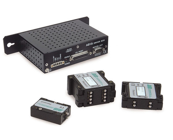
Image: Nanomotion Ltd.
Limitation 1: Speed
Ultrasonic piezoelectric motors operate by transferring vibrational energy at a friction contact into macroscopic motion. The maximum speed of this transfer is set by the vibration amplitude, the resonant frequency of the piezo element, and the contact mechanics.
For commercial ultrasonic piezo linear motors, maximum velocity is typically:
- Standing-wave (inertia/stick-slip) designs: 10 to 100 mm/s
- Traveling-wave designs: 50 to 300 mm/s
- Resonant-bar designs: 20 to 200 mm/s
Some specialized designs reach 500 mm/s in short bursts, but sustained operation above 300 mm/s is rare in production products.
Compare this to electromagnetic alternatives:
- Servo motor with ball screw: 100 to 2,000 mm/s sustained
- Direct-drive linear servo: 500 to 5,000 mm/s sustained
- Stepper motor with lead screw: 50 to 500 mm/s sustained
The speed gap is fundamental, not merely a manufacturing limitation. The friction contact in a piezo motor dissipates energy at a rate proportional to the relative sliding velocity. At high speeds, the contact either overheats (degrading the friction material) or the coupling efficiency drops (the contact cannot transfer energy fast enough to maintain the commanded velocity). Either way, the motor enters a regime where it is inefficient and wearing rapidly.
When Speed Disqualifies Piezo
High-throughput inspection and metrology. Semiconductor wafer inspection, flat-panel display testing, and printed circuit board inspection require scanning velocities of 200 to 2,000 mm/s over stage travels of 200 to 600 mm. These are direct-drive linear servo applications, period. No piezo motor can sustain the required velocity over the required stroke with acceptable lifetime.
Pick-and-place assembly. Modern chip placement machines move at 500 to 1,500 mm/s with acceleration exceeding 10 g. The combination of high speed, high acceleration, and high duty cycle is far beyond the capability of any piezo motor.
CNC machining and 3D printing. Rapid traverse speeds of 200 to 500 mm/s are standard. The sustained high-speed, high-force motion profile is a natural fit for servo motors, and there is no precision advantage to using piezo at these tolerance levels (typically 10 to 100 micrometers).
Conveyor and transport systems. Any application requiring continuous motion at constant velocity above 100 mm/s for hours or days. Piezo motor lifetime under sustained high-speed operation is measured in hundreds to low thousands of hours, not the tens of thousands expected of industrial systems.
The Speed Threshold Rule of Thumb
If your sustained velocity requirement exceeds 100 mm/s, investigate servo motor solutions first. Piezo motors should be considered only if another requirement (resolution, magnetic cleanliness, zero-power hold) overrides the speed limitation, and even then, expect reduced lifetime compared to lower-speed applications.
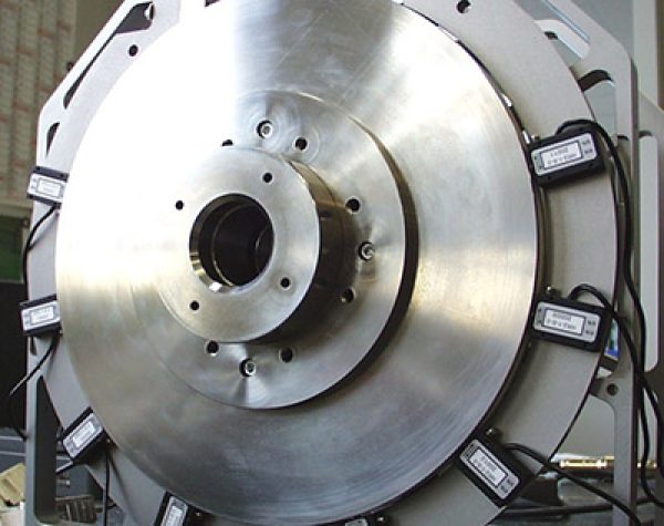
Image: Nanomotion Ltd.
Limitation 2: Force
Ultrasonic piezo linear motors produce force through friction coupling. The drive force is the product of the normal preload (clamping force pressing the piezo element against the runner) and the effective dynamic friction coefficient. For typical ceramic-on-ceramic or ceramic-on-metal contacts:
- Preload: 5 to 50 N per contact point
- Effective friction coefficient: 0.1 to 0.3
- Drive force per contact: 0.5 to 15 N
Multiple contact points can increase force. A motor with four contact elements producing 5 N each delivers 20 N total. Some manufacturers achieve 50 to 100 N with arrays of contact elements, but these are large, heavy, and expensive.
Compare to electromagnetic alternatives:
- NEMA 17 stepper with 2 mm lead screw: 100 to 500 N
- NEMA 23 servo with 5 mm ball screw: 500 to 5,000 N
- NEMA 34 servo with roller screw: 5,000 to 50,000 N
- Direct-drive linear servo (iron-core): 100 to 5,000 N continuous
The force gap is large: 10x to 1,000x for motors of comparable physical size.
Piezo stack actuators can produce enormous forces (up to 30,000 N for large stacks), but only over microscopic strokes (5 to 150 micrometers). When the stack is amplified via a flexure mechanism to reach practical stroke (0.5 to 2 mm), the available force drops by the amplification ratio, typically to 50 to 500 N.
When Force Disqualifies Piezo
Machine tool feed axes. Cutting forces in milling, turning, and grinding range from 50 to 5,000 N. Even moderate machining operations exceed the force capability of any piezo motor. Servo motors with ball screws or roller screws are the established solution and will remain so.
Press and forming operations. Any application requiring sustained forces above 100 N over strokes above 10 mm. Hydraulic and electromechanical (servo + screw) actuators dominate.
Heavy load positioning. Moving stages or payloads weighing more than 5 to 10 kg on a vertical axis. The gravity load alone (50 to 100 N) consumes most or all of the piezo motor's force budget, leaving little margin for acceleration, friction, and disturbance rejection. Electromagnetic motors handle heavy loads routinely.
Acceleration-dominated profiles. If the application requires accelerating a 2 kg payload at 5 g (approximately 100 N), a piezo motor with 10 N drive force simply cannot do it. Servo motors achieve this routinely.
The Force Threshold Rule of Thumb
If continuous force requirement exceeds 20 N, or peak force requirement exceeds 50 N, servo motors are almost always the better choice for travel above 10 mm. Piezo stacks can deliver thousands of newtons, but only for sub-millimeter strokes.
Limitation 3: Cost at Volume
At low volume (1 to 100 units), the cost comparison between piezo and electromagnetic solutions is often favorable to piezo when the precision requirement is high. A piezo motor stage with 50 nm resolution and 25 mm stroke costs $3,000 to $8,000. Achieving equivalent performance with a servo motor requires a direct-drive linear motor, air bearing, and interferometric encoder, totaling $15,000 to $50,000.
At high volume, the economics reverse.
Why Piezo Motors Do Not Scale as Well
Ceramic manufacturing. PZT ceramic elements require powder processing, sintering at 1,000 to 1,300 degrees Celsius, diamond dicing, electrode deposition, poling at elevated temperature and field, and testing. This is a batch process with limited automation compared to the stamping, winding, and magnetizing operations used for electromagnetic motor rotors and stators.
Friction contact assembly. The friction tip or pad must be bonded to the piezo element, preloaded against the runner, and adjusted for optimal contact force. This is a manual or semi-automated process requiring skilled technicians. Electromagnetic motors require no analogous hand-adjusted contact.
Precision flexure stages. The mechanical stage that accompanies a piezo motor (cross-roller guide, flexure bearing, preload mechanism) is precision-machined and assembled. For electromagnetic motors, commodity ball guides and ball screws provide equivalent guidance at a fraction of the cost.
Driver electronics. Piezo motor drivers are specialized, low-volume circuits. Servo and stepper drivers are commodity products manufactured in millions of units, with single-chip driver ICs costing $2 to $10.
Cost Comparison at Volume
The following estimates assume 10,000 units per year:
| Component | Stepper System | Servo System | Piezo Motor System |
|---|---|---|---|
| Motor | $8 to $20 | $30 to $80 | $30 to $100 |
| Driver electronics | $3 to $10 | $15 to $50 | $30 to $100 |
| Transmission (screw/guide) | $10 to $50 | $20 to $100 | N/A (direct drive) |
| Encoder/sensor | $0 (open-loop) or $5 to $20 | $10 to $30 | $20 to $80 |
| Mechanical stage | $5 to $30 | $10 to $50 | $50 to $200 |
| Assembly and test | $5 to $15 | $10 to $30 | $20 to $50 |
| Total per axis | $31 to $145 | $95 to $340 | $150 to $530 |
At 10,000 units, a piezo motor axis costs 2 to 5 times more than a stepper axis and 1.5 to 2 times more than a servo axis. The premium buys superior resolution, zero-power hold, and compact size. If those features do not add measurable value to the end product, the premium is waste.
When Cost Disqualifies Piezo
Consumer electronics. Devices with bill-of-materials targets below $500 and volumes above 100,000 units per year. Camera autofocus mechanisms are an exception (where piezo's speed and silence justify the premium), but most consumer motion applications use steppers or voice coils.
General industrial automation. Production line actuators, valve positioners, packaging machinery, and material handling. Stepper motors at $10 to $30 each dominate this space, and piezo motors at $50 to $200 cannot compete unless the application demands precision that steppers cannot deliver.
Robotics. Joint actuators for industrial and collaborative robots use servo motors for their combination of high torque, high speed, and moderate cost. Piezo motors cannot match the torque or speed requirements, and the cost premium is unjustified.
The Cost Rule of Thumb
If your production volume exceeds 1,000 units per year and your resolution requirement is above 5 micrometers, electromagnetic motors will almost always be cheaper. The cost crossover favoring piezo occurs only when the resolution requirement is below 1 micrometer, the environmental constraints favor non-magnetic solutions, or the zero-power hold eliminates the need for continuous power supply to the motor.
Limitation 4: Wear and Lifetime
This is the limitation that piezo motor manufacturers discuss least enthusiastically. The friction contact that enables piezo motor operation is also the mechanism that limits its life.
Wear Mechanisms
Adhesive wear. At the friction contact, microscopic asperities on the two surfaces bond momentarily under pressure and then shear apart. This removes material from both surfaces. The wear rate depends on preload force, sliding velocity, surface roughness, and material hardness.
Abrasive wear. Ceramic wear debris from the contact acts as an abrasive between the surfaces, accelerating wear. In enclosed designs, this debris accumulates and worsens the problem over time. In open designs, debris falls away but may contaminate the environment.
Fatigue wear. The repeated cyclic loading of the friction contact causes subsurface cracks that eventually produce large wear fragments. This mechanism becomes significant after millions of contact cycles.
Lifetime Numbers
Manufacturers specify lifetime in terms of cumulative travel distance (kilometers) or operating hours at rated speed. Typical values:
- Standing-wave (stick-slip) motors: 5,000 to 20,000 hours, or 1,000 to 10,000 km
- Traveling-wave rotary motors: 3,000 to 10,000 hours
- Resonant-bar linear motors: 5,000 to 20,000 hours, or 2,000 to 20,000 km
These numbers sound adequate but require context:
Industrial 24/7 operation: 20,000 hours is 2.3 years of continuous operation, or roughly 5 years at 50% duty cycle. Many industrial machines are expected to run for 10 to 20 years with periodic maintenance. Servo motors with ball screws, properly maintained and relubricated, achieve 30,000 to 100,000 hours. Piezo motors may need replacement one or more times during the machine's service life.
Laboratory instruments: Duty cycles are typically low (minutes of motion per day), so lifetime is rarely an issue. A piezo motor in a microscope stage that moves 100 mm per positioning cycle, 100 cycles per day, accumulates only 3.65 km per year. At that rate, even a 5,000 km lifetime corresponds to 1,370 years of operation.
Semiconductor equipment: Moderate duty cycle, but equipment uptime and maintenance cost are critical. Piezo motor replacement every 2 to 3 years is acceptable if the procedure is straightforward. If the motor is buried inside a vacuum chamber, replacement becomes a multi-day, multi-thousand-dollar maintenance event.
Wear Mitigation
Preload optimization. Reducing preload force reduces wear rate but also reduces drive force and holding force. The optimal preload balances performance against lifetime.
Speed derating. Operating below maximum rated speed extends life roughly proportionally. A motor rated for 200 mm/s and 10,000 km that operates at 50 mm/s will typically achieve 15,000 to 25,000 km due to the nonlinear relationship between speed and wear.
Material selection. Hard ceramic friction pairs (alumina on alumina, zirconia on alumina) wear slower than ceramic on metal. Some manufacturers use proprietary composite friction materials that optimize the tradeoff between friction coefficient and wear rate.
Environmental control. Humidity affects wear. In very dry environments (including vacuum), the absence of adsorbed moisture at the contact increases friction and wear. Some vacuum-compatible piezo motors include a small reservoir of friction-modifying material to compensate.
When Lifetime Disqualifies Piezo
High-duty-cycle industrial production. Any application running at or near maximum speed for more than 4,000 hours per year should carefully evaluate whether piezo motor lifetime is adequate. If motor replacement is difficult or costly (vacuum systems, embedded mechanisms), the lifetime limitation may disqualify piezo.
Inaccessible installations. Satellite mechanisms, deep-sea instruments, and other applications where motor replacement is impossible. Though piezo motors are used in space (for their low power and non-magnetic properties), lifetime qualification testing is extensive and application-specific.
Cost-sensitive high-wear applications. If the application consumes motor life rapidly (high speed, high preload, continuous duty), the recurring cost of piezo motor replacement may exceed the lifetime cost of a servo motor system that is inherently longer-lived.
Limitation 5: Simplicity and Ecosystem
Stepper motors and servo motors benefit from decades of ecosystem development. The implications are practical and significant:
Controller and Driver Availability
- Stepper drivers: Available from dozens of manufacturers at $5 to $100. Single-chip integrated driver ICs (e.g., TMC2209, DRV8825) cost $2 to $5 and are supported by Arduino, Raspberry Pi, and every major PLC platform.
- Servo drives: Available from dozens of manufacturers at $50 to $5,000. Supported by all major motion controller platforms (Beckhoff, Siemens, Delta, Mitsubishi, etc.) with plug-and-play configuration.
- Piezo motor drivers: Available from a handful of manufacturers at $200 to $2,000. Most piezo motor stages come with a proprietary driver and controller, often with a proprietary communication protocol. Integration into standard PLC systems may require custom interface development.
Mechanical Integration
- Stepper and servo motors: NEMA and IEC standardized frame sizes, shaft dimensions, and mounting patterns. Any NEMA 23 motor mounts in any NEMA 23 bracket. Ball screws, couplings, and linear guides have standardized dimensions from multiple suppliers.
- Piezo motor stages: Each manufacturer has proprietary form factors, mounting patterns, and connector types. Switching suppliers requires mechanical redesign. Multi-axis configurations often require custom brackets.
Engineering Knowledge Base
- Stepper and servo motors: Taught in undergraduate engineering curricula. Covered by dozens of textbooks. Supported by active online communities. Any mechanical engineer can size a servo motor for a ball screw application. Application engineers at motor manufacturers provide free design assistance.
- Piezo motors: Covered briefly in specialized courses. Fewer textbooks. Smaller community. Sizing and selection often require direct engagement with the manufacturer's application engineering team. This is not a criticism of the technology; it is a practical consideration for project schedules and risk management.
When Simplicity Disqualifies Piezo
Rapid prototyping and development. When the project timeline does not allow for learning a new actuator technology, and the precision requirement does not demand it, using a familiar servo or stepper is the pragmatic choice.
Systems with many axes. A machine with 20 linear axes needs standardized, interchangeable components. Servo motors with common drives and controllers provide this. Twenty piezo motor axes from three different manufacturers, each with a different driver, creates an integration and maintenance challenge.
Field service requirements. If the end product will be serviced by technicians with standard training, stepper and servo motors are replaceable with commodity parts. Piezo motors require specific part numbers from specific suppliers, with lead times of 4 to 12 weeks.
A Realistic Assessment Matrix
| Application | Use Piezo? | Why or Why Not |
|---|---|---|
| Semiconductor wafer scanning | No | Speed (1,000+ mm/s) and stroke (300+ mm) exceed piezo capability. Use direct-drive servo. |
| Semiconductor reticle alignment | Yes | Sub-100 nm precision, short stroke, cleanroom, low speed. Piezo is ideal. |
| CNC milling machine | No | High force (500+ N), high speed, large stroke. Servo + ball screw. |
| Optical fiber alignment | Yes | Sub-micrometer precision, low force, low speed, compact. Piezo is ideal. |
| 3D printer | No | Resolution (50+ micrometers) easily met by steppers at 1/10 the cost. |
| Electron microscope stage | Yes | Magnetic cleanliness, vibration, resolution. Piezo is the standard choice. |
| Industrial robot joint | No | High torque, high speed, standardized ecosystem. Servo motor, always. |
| Satellite antenna pointing | Yes (maybe) | Low power, non-magnetic, compact. But lifetime qualification is expensive. Evaluate case-by-case. |
| Consumer camera autofocus | Yes (voice coil preferred for most; piezo for specific cases) | Voice coils and MEMS actuators dominate this market on cost. Piezo is used in high-end video lenses. |
| Laboratory micropositioning | Yes | Resolution, low noise, zero-power hold. The classic piezo application. |
| Packaging machinery | No | High speed, moderate precision, cost sensitivity, 24/7 operation. Stepper or servo. |
| MRI-compatible biopsy robot | Yes | Non-magnetic is non-negotiable. Piezo or pneumatic; piezo has better precision. |
The Honest Summary
Piezoelectric motors and actuators are superior to electromagnetic alternatives in a specific performance envelope: sub-micrometer resolution, sub-50 mm/s speed, sub-20 N force, compact size, zero-power hold, zero magnetic emission, and environmentally constrained operation (vacuum, cleanroom, MRI).
Outside that envelope, they are inferior. They are slower, weaker, more expensive at volume, shorter-lived, and harder to integrate than servo motors. Using piezo where servo would suffice is like using a scanning electron microscope to inspect a weld bead: technically impressive, practically foolish.
The skill in motor selection is not knowing what each technology can do. It is knowing what each technology should not be asked to do. A piezo motor asked to move 200 mm/s continuously under 100 N of load will deliver poor performance, short life, and high cost. A servo motor asked to hold a position to 50 nm with no magnetic field emission will also fail, but differently.
Match the physics to the requirements. When the requirements call for piezo, there is no substitute. When they do not, there is no reason to pay the premium.
The best motor for any application is the simplest, cheapest, and most reliable one that meets all the actual requirements. Sometimes that is a piezo motor. Often, it is not. Honesty about that distinction is what separates engineering from sales.