Technology
EMI, magnetic fields, and cleanroom compatibility: a technology comparison
Quantitative analysis of electromagnetic interference, stray magnetic fields, particle generation, and outgassing across actuator technologies
EMI, Magnetic Fields, and Cleanroom Compatibility: A Technology Comparison
In a standard industrial environment, the electromagnetic and particulate characteristics of a motor rarely influence the technology selection. The motor sits in an enclosure, the cables run through conduit, and the factory air has enough particles that a few more from the motor are irrelevant.
Precision applications are different. Electron microscopes cannot tolerate stray magnetic fields above 0.1 microtesla (1 milligauss). Semiconductor fabs require particle counts below 100 per cubic meter at 0.1 micrometer size (see vacuum and cleanroom operation for details). MRI suites enforce strict magnetic field homogeneity zones. Sensitive RF receivers detect microvolt-level conducted emissions.
In these environments, the motor technology becomes a compatibility question as much as a performance question. The technology selection framework addresses environment as one of the five decision criteria. This article provides measured values and practical thresholds for five actuator technologies across four environmental parameters: stray magnetic fields, electromagnetic interference (EMI), particle generation, and outgassing.
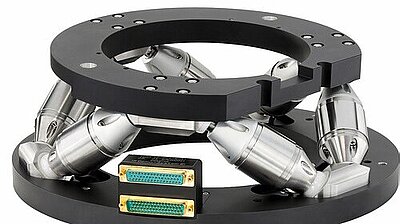
Image: Physik Instrumente (PI)
Stray Magnetic Fields
Sources of Magnetic Emission
All electromagnetic motors contain two magnetic field sources: permanent magnets and current-carrying conductors.
Permanent magnets (typically NdFeB or SmCo) produce a static (DC) magnetic field that is always present, regardless of whether the motor is operating. The field strength at a distance depends on the magnet geometry, magnetization, and any shielding. For a dipole approximation, the field drops as 1/r^3, where r is the distance from the magnet center.
Current-carrying conductors produce a magnetic field proportional to current. In a well-designed motor, the conductor geometry is arranged so that fields from different conductors partially cancel in the far field, but cancellation is imperfect. The field from conductors drops as 1/r^2 for a current loop.
Piezoelectric actuators contain neither permanent magnets nor current-carrying coils during static operation. During motion, the piezo driver cable carries current, but at ultrasonic frequencies (20 to 200 kHz) rather than the low frequencies (DC to a few kHz) that are problematic for most magnetically sensitive instruments.
Measured Field Values by Technology
The following values represent typical stray magnetic flux density at 100 mm from the motor center, measured with a fluxgate magnetometer. These are representative values; specific products vary by a factor of 2 to 5 depending on design.
| Technology | DC Field (from magnets) | AC Field (from current, at rated operation) |
|---|---|---|
| Stepper motor (NEMA 17) | 0.5 to 2 mT | 0.1 to 0.5 mT (at step frequency) |
| Servo motor (60 mm frame BLDC) | 0.3 to 1.5 mT | 0.05 to 0.3 mT (at commutation frequency) |
| Voice coil actuator | 1 to 5 mT | 0.01 to 0.1 mT |
| Direct-drive linear servo (iron-core) | 2 to 10 mT | 0.1 to 1 mT |
| Direct-drive linear servo (ironless) | 0.5 to 3 mT | 0.05 to 0.2 mT |
| Piezo motor | < 0.001 mT | < 0.01 mT (at ultrasonic frequency) |
| Piezo stack actuator | < 0.001 mT | < 0.001 mT |
Environmental Thresholds
Electron microscopy (SEM, TEM): Maximum allowable AC magnetic field disturbance is typically 0.03 to 0.1 microtesla (0.3 to 1 milligauss) at the column, depending on the instrument and required resolution. At 100x magnification, a 0.1 microtesla field causes negligible image distortion. At 100,000x magnification, it causes visible beam deflection.
To meet a 0.1 microtesla requirement at the column, an electromagnetic motor must be either:
- Located far from the column (typically 0.5 to 2 m, depending on motor size)
- Enclosed in a magnetic shield (mu-metal, 1 to 3 layers, providing 20 to 60 dB attenuation)
- Replaced with a non-magnetic actuator
Piezo motors and piezo stacks meet the 0.1 microtesla threshold at distances of 10 mm or less, with no shielding required.
SQUID magnetometry: SQUIDs detect fields in the femtotesla range. Any permanent magnet within several meters is problematic. Even "non-magnetic" materials (stainless steel screws, nickel-plated connectors) can disturb measurements. Piezo actuators with fully non-magnetic construction (titanium, ceramic, aluminum, plastic) are the only motor technology usable in a SQUID system.
MRI environments: Within the MRI room, ferromagnetic materials are both a safety hazard (projectile risk) and a field homogeneity concern. MRI-compatible motors must be non-ferromagnetic. Pneumatic actuators and ultrasonic piezo motors are the two standard solutions. Servo and stepper motors are absolutely excluded unless located outside the MRI room with non-magnetic transmission linkages.
Atom trapping and ion trapping: Magnetic field stability requirements of 0.1 to 10 microtesla are common. Electromagnetic motors within 0.5 m of the trapping region require active field cancellation or magnetic shielding. Piezo motors and stacks are used routinely in these systems without shielding.
Shielding Options and Their Costs
When an electromagnetic motor must be used in a magnetically sensitive environment, shielding is the standard mitigation. Common approaches:
Mu-metal enclosures: 1 to 3 layers of high-permeability nickel-iron alloy surrounding the motor. Attenuation of 20 to 40 dB per layer for DC and low-frequency AC fields. Cost: $500 to $5,000 per motor, depending on size and shielding effectiveness. Weight: adds 50% to 200% of motor weight. The enclosure must be carefully designed with proper seam geometry and no large apertures.
Active cancellation: Helmholtz or saddle coils driven by a feedback magnetometer to cancel the motor's stray field. Attenuation of 20 to 40 dB at frequencies below the feedback bandwidth (typically 100 Hz to 1 kHz). Cost: $2,000 to $20,000 for a custom cancellation system. Complexity: high, and the cancellation system itself consumes power and generates heat.
Distance: The simplest mitigation. Moving the motor 3x further away reduces the field by roughly 27x (1/r^3 for dipole). A motor at 100 mm with 1 mT stray field produces approximately 0.037 mT at 300 mm. Cost: zero, but may not be mechanically practical.
The engineering insight is that shielding a $200 stepper motor with a $2,000 mu-metal enclosure often costs more than replacing it with a $3,000 piezo motor stage that needs no shielding.
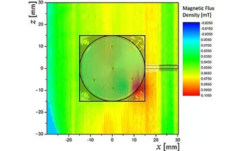
Image: Physik Instrumente (PI)
Electromagnetic Interference (EMI)
EMI encompasses both conducted emissions (noise on power and signal cables) and radiated emissions (electromagnetic waves from the motor and cables). Sensitive instruments (RF receivers, precision ADCs, lock-in amplifiers, NMR probes) can be disrupted by EMI from nearby motors.
EMI Sources by Technology
Stepper motors: Driven by chopped-current H-bridge drivers that switch at 20 to 100 kHz. Each switching event generates broadband EMI with spectral content from the switching frequency to 100+ MHz. Conducted emissions on the motor cables are typically 50 to 80 dBuV in the 150 kHz to 30 MHz range (before filtering). Radiated emissions depend on cable routing and shielding.
Servo motors: Similar to steppers but often with higher switching frequencies (10 to 100 kHz PWM) and higher power. Field-oriented control (FOC) drives produce cleaner current waveforms than stepper drivers, reducing harmonic content. Conducted emissions: 40 to 70 dBuV (150 kHz to 30 MHz).
Voice coil actuators: Driven by linear amplifiers or low-frequency PWM. Linear amplifiers produce minimal EMI. PWM drivers produce EMI similar to servo drives but typically at lower power levels. Conducted emissions (linear driver): 20 to 40 dBuV. Conducted emissions (PWM driver): 40 to 60 dBuV.
Piezo stack actuators: Driven by linear high-voltage amplifiers (for small signals) or switched-mode amplifiers (for high-power applications). Linear amplifiers are extremely quiet electrically. Switched-mode piezo amplifiers operate at 50 to 500 kHz and produce conducted emissions of 40 to 60 dBuV. The high-voltage cables (100 to 150 V) can radiate if not properly shielded.
Ultrasonic piezo motors: The driver generates a high-frequency signal (20 to 200 kHz, typically 10 to 50 V) to excite the ceramic resonator. The spectral content is concentrated in a narrow band around the resonant frequency and its harmonics. Conducted emissions: 30 to 50 dBuV, concentrated at discrete frequencies rather than broadband. This narrow-band signature is easier to filter than the broadband EMI from chopped-current motor drivers.
EMI Mitigation Strategies
Shielded cables: The most effective single measure. Shielded motor cables with proper grounding reduce radiated emissions by 30 to 60 dB. Cost: $5 to $20 per meter premium over unshielded cable.
Ferrite cores: Common-mode chokes on motor cables suppress high-frequency conducted emissions. Attenuation: 10 to 20 dB at 1 to 100 MHz. Cost: $2 to $10 per cable.
EMI filters: LC or pi filters at the motor driver output suppress switching harmonics. Attenuation: 20 to 60 dB depending on filter order and frequency. Cost: $10 to $100.
Physical separation: Every doubling of distance reduces radiated field strength by 6 dB. Moving the motor driver 1 m from sensitive electronics is often the simplest and most effective EMI mitigation.
Linear amplifiers: For the most sensitive applications, driving the actuator with a linear (non-switching) amplifier eliminates switching EMI entirely. Linear amplifiers are available for voice coils and piezo stacks. Efficiency is lower (40% to 60% versus 85% to 95% for switching types), and heat generation is higher.
Cleanroom Compatibility: Particle Generation
Particle Sources in Motion Systems
Particle generation from motion systems comes from:
-
Sliding contacts: Ball screw nut, lead screw nut, recirculating ball bearings in linear guides, and motor brushes (if any). Each sliding contact generates particles from abrasion of the contact surfaces and their lubricants.
-
Lubricant degradation: Grease and oil lubricants break down over time, producing volatile organic compounds and particulate debris. In vacuum, lubricant evaporation adds to this problem.
-
Cable flexing: As cables bend during stage motion, the insulation and jacket materials generate particles from surface abrasion. Cable carriers (energy chains) generate particles from the chain link contacts.
-
Friction drive contacts (piezo motors): The ceramic-on-ceramic or ceramic-on-metal contact in ultrasonic piezo motors generates wear debris. This is a significant consideration for cleanroom use.
-
Outgassing condensation: Volatile compounds from adhesives, potting materials, and plastic components can condense on nearby surfaces as molecular contamination, which is a cleanroom concern distinct from particle contamination.
Particle Generation Rates by Technology
Particle generation data for actuators is sparse in the published literature. The following values are based on available manufacturer test data and independent measurements, expressed as particles per minute greater than 0.1 micrometer in size, measured in a Class 1 (ISO 3) laminar flow environment.
| Technology | Particle Source | Particles/min (> 0.1 um) | Cleanroom Class Achievable |
|---|---|---|---|
| Stepper + lead screw + ball guide | Screw nut, guide balls | 100 to 10,000 | ISO 5 to 7 |
| Stepper + lead screw + flexure guide | Screw nut, cable flexure | 10 to 1,000 | ISO 4 to 6 |
| Servo + ball screw + ball guide | Screw nut, guide balls, motor bearings | 100 to 10,000 | ISO 5 to 7 |
| Servo + ball screw + flexure guide | Screw nut, cable flexure | 10 to 1,000 | ISO 4 to 6 |
| Direct-drive servo + air bearing | Cable flexure, air supply particles | 1 to 100 | ISO 3 to 5 |
| Voice coil + flexure | Cable flexure | 1 to 50 | ISO 3 to 5 |
| Piezo motor + flexure guide (short stroke) | Friction contact, cable flexure | 1 to 100 | ISO 3 to 5 |
| Piezo motor + crossed-roller guide (long stroke) | Friction contact, roller guide, cable | 10 to 500 | ISO 4 to 6 |
| Piezo stack + flexure | Cable flexure only | 0.1 to 10 | ISO 2 to 4 |
Key Observations
Ball screws are the dominant particle source in conventional servo and stepper systems. The recirculating ball mechanism grinds lubricant and ball surface material continuously. Sealed ball screw nuts with filtered purge air reduce but do not eliminate particle generation. For ISO Class 5 and cleaner environments, ball screws require either enclosure with exhaust or replacement with a direct-drive architecture.
Piezo motor friction contacts generate particles, but the quantity is typically 10 to 100 times less than a ball screw because the contact area is much smaller, velocities are lower, and the ceramic materials are harder than steel. However, the particles are ceramic (alumina, zirconia) and can be harder and more abrasive than metal particles, potentially causing more damage to sensitive surfaces if they land on a wafer or optical element.
Flexure-guided piezo stack stages are the cleanest option because they have zero sliding contacts. The only particle sources are cable flexure and, potentially, outgassing condensation from adhesives in the stack and flexure assembly. With appropriate material selection (cyanoacrylate-free adhesives, PEEK or polyimide cable insulation), ISO Class 2 compatibility is achievable.
Cable management is the often-overlooked particle source that affects all technologies equally. A cable carrier (energy chain) with 10 cables cycling at 1 Hz can generate 100 to 1,000 particles per minute. Solutions include: routed flat-flex cables (fewer particles than round cables), cable tracks with PTFE liners, or cable-free designs (not usually practical for multi-axis systems).
Cleanroom Design Recommendations
ISO Class 7 (Class 10,000) and dirtier: Any motor technology is acceptable with standard precautions (cleanroom-compatible grease, sealed bearings, cable carriers with covers).
ISO Class 5 (Class 100): Avoid ball screws if possible. Use flexure-guided or air-bearing stages. If ball screws are necessary, enclose them with filtered exhaust. Piezo motor stages with flexure guides are well-suited.
ISO Class 4 (Class 10) and cleaner: Use flexure-guided piezo stacks, air-bearing stages, or voice coil stages with flexure guides. Minimize cable motion. Select materials with documented cleanroom compatibility. Test the assembled stage in a particle counter before deployment.
ISO Class 3 (Class 1): Every component matters. Use piezo stack flexure stages or air-bearing direct-drive stages with ultraclean assembly, bake-out, and validated materials. Even the position sensor cable can be a significant particle source.
Outgassing
Outgassing matters in two contexts: vacuum systems (where outgassing degrades vacuum level) and cleanroom environments (where molecular contamination deposits on product surfaces).
Outgassing Sources
The primary outgassing sources in actuator assemblies are:
- Adhesives: Epoxies, cyanoacrylates, silicones. Total mass loss (TML) of 0.5% to 5% depending on cure conditions and type.
- Wire insulation: PVC (high outgassing), polyethylene (moderate), polyimide/Kapton (low), PTFE (very low).
- Lubricants: Mineral oil and lithium grease (high), PFPE (Fomblin/Krytox, low), MoS2 dry lubricant (very low).
- Potting compounds: Silicone potting (high outgassing of siloxanes), epoxy potting (moderate after cure), unfilled cavities (lowest).
- Plastic components: Nylon, Delrin, ABS (moderate to high), PEEK, Vespel, Torlon (low).
- Piezo ceramic elements: Extremely low outgassing. Sintered ceramic is essentially gas-free after a standard vacuum bake-out.
Outgassing Comparison by Technology
| Technology | Primary Outgassing Sources | Typical TML (% after 24h at 125C) | Vacuum Suitability |
|---|---|---|---|
| Stepper motor | Wire insulation, grease, potting | 0.5% to 2% | HV with modification |
| Servo motor | Wire insulation, grease, potting, magnets coating | 0.5% to 2% | HV with modification |
| Voice coil | Wire insulation, adhesive, potting | 0.3% to 1.5% | HV to UHV with selection |
| Piezo motor (standard) | Friction pad material, adhesive, wire insulation | 0.2% to 1% | HV |
| Piezo motor (vacuum-grade) | Friction pad, ceramic adhesive | 0.05% to 0.3% | UHV (10^-9 mbar) |
| Piezo stack (standard) | Stack adhesive, wire insulation | 0.1% to 0.5% | HV |
| Piezo stack (UHV-grade) | Minimal (ceramic, metal, glass) | < 0.05% | UHV (10^-10 mbar) |
Practical Vacuum Guidelines
Rough vacuum (above 10^-3 mbar): All technologies work with standard cleanroom-grade lubricants and vacuum-rated cables.
High vacuum (10^-3 to 10^-8 mbar): Replace standard lubricants with PFPE types. Use polyimide-insulated cables. Bake out at 80 to 150 degrees Celsius for 24 to 48 hours. Stepper and servo motors require vacuum-rated versions (special grease, vacuum-rated connectors, no potting). Piezo motors and stacks are easier to qualify because they have fewer organic materials.
Ultra-high vacuum (below 10^-8 mbar): Material-by-material qualification is necessary. UHV-grade piezo stacks use ceramic-to-metal brazing (no organic adhesive), glass-sealed electrical feedthroughs, and bare ceramic surfaces. UHV piezo motors use specialized friction materials (e.g., alumina on alumina) and ceramic adhesives. Servo motors in UHV are rare and expensive; they require all-metal construction, MoS2 dry lubrication, and extensive bake-out.
Which Technology for Which Environment?
Electron Microscopy (SEM/TEM/FIB)
Primary concerns: Magnetic field, vibration, EMI. Best technology: Piezo motor (for specimen stages, aperture positioning) or piezo stack (for fine focus, stigmator, beam blanking). Rationale: Zero magnetic emission eliminates beam deflection. Zero power at hold eliminates thermal drift. Ultrasonic drive frequency is above the bandwidth of beam deflection circuits. Common practice: Most modern electron microscope manufacturers use piezo stages for specimen positioning.
Semiconductor Fabrication
Primary concerns: Particles, outgassing, magnetic field (for ion implant and e-beam tools), speed. Best technology: Air-bearing direct-drive linear servo for wafer stages (speed and stroke requirements dominate). Piezo motor or piezo stack for reticle stages, alignment, and metrology (resolution and cleanliness dominate). Rationale: Wafer stages must move at 500+ mm/s over 300+ mm stroke, which only direct-drive servos can deliver. Secondary stages prioritize cleanliness and resolution.
MRI-Compatible Medical Devices
Primary concerns: Magnetic field (safety and image artifact), EMI (RF interference with imaging). Best technology: Ultrasonic piezo motor with non-magnetic construction and fiber-optic encoder. Rationale: Zero magnetic materials, zero DC magnetic field emission, EMI concentrated at ultrasonic frequencies outside the MRI RF bandwidth. Pneumatic actuators are an alternative but lack precision.
Optical Metrology Labs
Primary concerns: Vibration, thermal stability, EMI (interference with photodetectors). Best technology: Piezo stack for sub-mm positioning; piezo motor for longer travel. Voice coil for active vibration isolation. Rationale: Zero-power hold eliminates thermal disturbance. Low vibration preserves measurement stability. Low EMI avoids interference with sensitive photodetectors and lock-in amplifiers.
Space and Satellite Systems
Primary concerns: Outgassing, power consumption, mass, radiation tolerance, magnetic cleanliness. Best technology: Piezo motor for mechanisms (antenna pointing, instrument deployment, optical alignment). Piezo stack for fine alignment. Rationale: Zero-power hold conserves spacecraft power. Low mass reduces launch cost. Low outgassing preserves optical surface cleanliness. No magnetic interference with science instruments.
Practical Decision Checklist
When evaluating motor technologies for environmentally constrained applications, work through this checklist:
-
Is there a magnetic field budget for the region near the motor? If the budget is below 0.01 mT at the motor location, only piezo technologies qualify without shielding.
-
Is the application in vacuum? If below 10^-6 mbar, prefer piezo motors or stacks with vacuum-grade construction. Budget for bake-out and material qualification.
-
Is the application in an ISO Class 5 or cleaner environment? Avoid ball screws and lead screws. Use flexure-guided stages. Consider particle testing of the selected stage before deployment.
-
Is the application near sensitive RF or precision analog electronics? Characterize the EMI spectrum of the motor driver. Use shielded cables, ferrite cores, and (if necessary) linear amplifiers.
-
What is the acceptable thermal load in the motor's local environment? In vacuum, any heat from the motor must be conducted away through the mounting structure. In thermally sensitive optical systems, even 1 W of continuous dissipation can cause measurable drift.
-
Can the motor be located remotely? Sometimes the best solution is to place the motor far from the sensitive region and use a mechanical linkage (shaft, cable, belt) to transmit motion. This trades mechanical precision for environmental compatibility.
The cleanest, most magnetically quiet, most thermally stable motor technology is the one that is not there. Piezoelectric actuators come closest to that ideal: no magnets, no continuous current, no heat at hold, minimal particles, minimal outgassing. When the environment demands it, the choice is often straightforward.