Fundamentals
Vacuum and cleanroom operation: why piezo outperforms electromagnetic alternatives
Outgassing, particle generation, magnetic interference, and design strategies for UHV and EUV environments
Semiconductor fabs, synchrotron beamlines, and space simulation chambers all share a common constraint: the motion system must not contaminate the process environment. Electromagnetic motors, the workhorse of general automation, introduce outgassing polymers, generate magnetic fields that distort electron beams, and shed ferromagnetic particles that become killer defects on wafers. For semiconductor-specific vacuum motor selection, see the vacuum motor selection guide. Ultrasonic piezoelectric motors sidestep most of these problems by design. Their operating principle requires no coils, no permanent magnets, and no lubricants, making them a natural fit for vacuum and cleanroom service. This article examines why, and where the remaining engineering challenges lie.
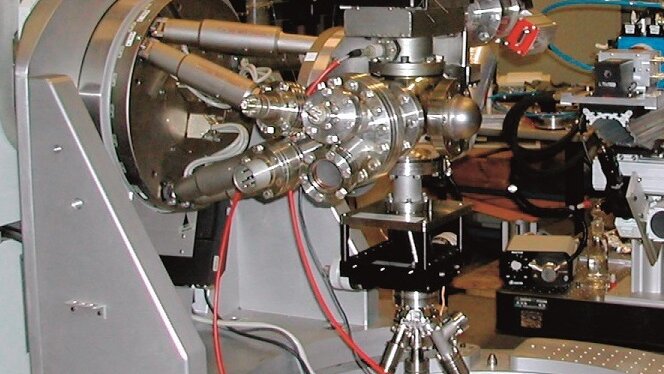
Image: Physik Instrumente (PI)
The contamination problem in vacuum and cleanroom systems
Every component placed inside a vacuum chamber or cleanroom tool contributes to the contamination budget. The two primary concerns are molecular contamination (outgassing) and particulate contamination. A third concern, specific to charged-particle instruments and EUV lithography, is stray magnetic fields.
Outgassing fundamentals
Understanding thermal behaviour is important here because bakeout temperatures affect motor performance. Outgassing rate is measured in Pa·m/s (or the older Torr·L/s·cm² convention). Materials with outgassing rates below 10⁻⁸ Pa·m/s are generally acceptable for high vacuum (HV, 10⁻⁴ to 10⁻⁷ Pa). Ultra-high vacuum (UHV, below 10⁻⁷ Pa) demands rates below 10⁻¹⁰ Pa·m/s after bakeout. The main offenders in conventional motor assemblies are:
- Epoxy potting compounds used to encapsulate stator windings. Typical epoxies outgas at 10⁻⁶ Pa·m/s even after moderate baking.
- Wire insulation (polyimide, polyester, PVC). Polyimide is the best of these at roughly 10⁻⁷ Pa·m/s after 150 °C bakeout, but PVC is orders of magnitude worse.
- Lubricants in bearings. Hydrocarbon greases are wholly incompatible with UHV. Even vacuum-rated PFPE lubricants (Fomblin, Krytox) contribute measurable partial pressures of fluorinated fragments above 10⁻⁸ Pa.
- Adhesives and potting used to bond magnets to rotors in brushless DC motors.
Particulate generation
Particles above 10 nm in diameter are a concern in advanced semiconductor lithography. ISO 14644-1 Class 1 cleanrooms permit no more than 10 particles ≥ 0.1 µm per cubic metre. Sources of particles in motion systems include:
- Bearing wear debris (steel, ceramic, or polymer cage material)
- Brush or commutator erosion in brushed DC motors
- Magnetic attraction of ferrous particles to permanent magnets
- Cable flexure abrasion
- Friction pad wear in piezo motors (the one vulnerability of piezo systems; discussed below)
Why electromagnetic motors struggle in vacuum
Outgassing from windings
An electromagnetic motor is fundamentally a coil of insulated wire wound around a ferromagnetic core. The wire insulation, the bobbin material, and the adhesive or varnish holding the windings in place all outgas. Replacing standard magnet wire with UHV-compatible alternatives (bare or ceramic-insulated wire) is possible but dramatically increases cost and reduces reliability. The coil must also be potted or mechanically restrained to prevent wire movement under Lorentz forces, and the potting compound adds yet another outgassing source.
Manufacturers of vacuum-compatible voice coil and stepper motors mitigate outgassing by using low-outgassing epoxies (NASA-qualified per ASTM E595, with TML < 1.0% and CVCM < 0.1%) and baking assemblies at 100 to 150 °C for 24 to 72 hours. This works for HV service but is often insufficient for UHV without additional compromises.
Magnetic field emission
Permanent-magnet motors (brushless DC, voice coil) generate stray magnetic fields that extend well beyond the motor housing. A typical 20 W brushless DC motor can produce stray fields of 0.5 to 5 mT at 50 mm from the motor surface. For context:
- Scanning electron microscopes require ambient fields below 50 nT for high-resolution imaging.
- EUV lithography tools specify stray fields below 0.1 µT at the wafer plane.
- Magnetic storage media and MRAM fabrication processes are sensitive to fields above 1 µT.
Shielding with mu-metal reduces stray fields by factors of 100 to 1000, but the shields add mass, volume, and cost. They also trap heat, exacerbating thermal management problems.
Heat dissipation
In atmosphere, convective and radiative cooling dissipate motor heat with modest thermal design effort. In vacuum, convection vanishes. A motor that runs at 40 °C in air may reach 150 °C or higher in vacuum, accelerating outgassing and risking demagnetization of NdFeB magnets (which begin to lose flux above 80 to 150 °C depending on grade). Thermal straps, heat sinks conducted to the chamber wall, and duty-cycle limits all become necessary.
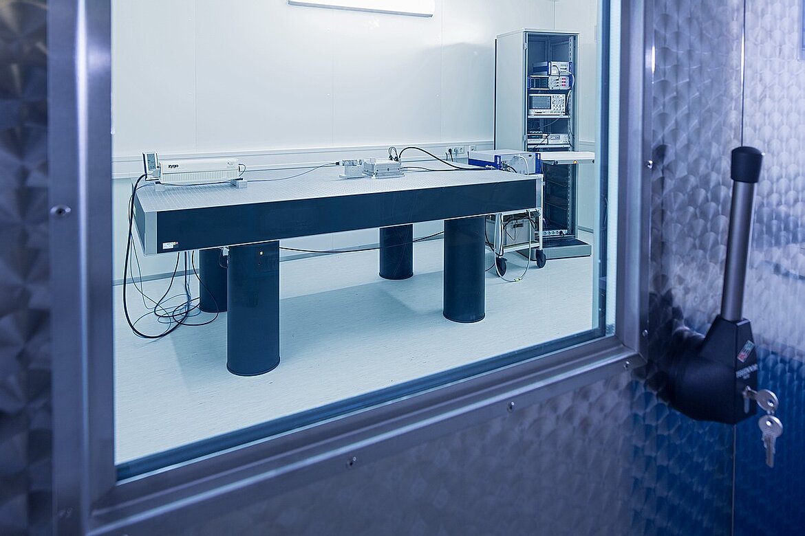
Image: Physik Instrumente (PI)
The piezo advantage
Ultrasonic piezoelectric motors operate by exciting a mechanical resonance in a ceramic or metal stator, then coupling that vibration to a rotor or slider through a friction interface. This mechanism confers several inherent advantages for vacuum and cleanroom use.
Zero magnetic field emission
Piezoelectric ceramics (PZT, lithium niobate, lead-free alternatives) are dielectric materials. They produce no magnetic field during operation. The drive electronics sit outside the vacuum chamber, connected by simple coaxial cables. The in-vacuum components, stator, friction tip, and preload spring, are all non-magnetic. Stray field contribution from a piezo stage is effectively zero, limited only by the permeability of the structural metals (typically non-magnetic stainless steel or titanium).
This makes piezo motors the default choice for electron-beam instruments, ion-beam systems, and any tool where magnetic cleanliness is required.
Minimal outgassing sources
A typical ultrasonic piezo motor assembly in vacuum consists of:
- PZT ceramic elements, bonded to a metal stator with a thin adhesive layer. PZT itself outgasses very little; the ceramic is dense and non-porous. Outgassing rates for fired PZT are in the 10⁻¹⁰ to 10⁻¹¹ Pa·m/s range.
- Metal stator body, usually stainless steel, titanium, or phosphor bronze. Metals are low-outgassing after standard cleaning and bakeout.
- Friction tip, typically alumina (Al₂O₃) or silicon nitride (Si₃N₄). These ceramics are effectively zero-outgassing.
- Preload spring, stainless steel or beryllium copper. Negligible outgassing.
- Adhesive layer bonding the PZT to the stator. This is the single largest outgassing contributor in the assembly. Low-outgassing epoxies or solder bonding can reduce this to acceptable levels.
- Electrical connections: fine wires (often bare or polyimide-insulated) soldered to the PZT electrodes.
The total outgassing budget of a well-designed piezo motor assembly can be kept below 10⁻⁹ Pa·m/s, making it compatible with UHV without heroic measures. Some manufacturers achieve 10⁻¹⁰ Pa·m/s after bakeout at 120 °C.
No lubricants required
The friction interface in an ultrasonic motor is a dry ceramic-on-ceramic or ceramic-on-metal contact. No lubricant is needed or desired; lubrication would actually degrade motor performance by reducing the friction coefficient that drives the motor. This eliminates one of the most problematic contamination sources in vacuum motion systems.
Bearings for the guided axis (linear rails, crossed rollers) do require attention. In vacuum, these are typically run dry with ceramic balls and stainless races, or replaced with flexure bearings that have zero particle generation. Flexure-guided piezo stages are particularly common in UHV applications.
The remaining challenges: particle generation and wear
The friction interface that makes piezo motors lubricant-free also makes them particle generators. The contact between the stator tip and the drive surface (the "runner") involves microscopic wear. Alumina-on-alumina contacts produce fine ceramic particles in the 0.1 to 10 µm range. The generation rate depends on:
- Contact force (preload). Higher preload increases force output but accelerates wear.
- Duty cycle. Continuous operation generates more debris than intermittent positioning.
- Surface finish. Polished interfaces wear more slowly than ground surfaces.
- Materials pairing. Alumina on alumina wears differently than alumina on hard-anodized aluminum or alumina on silicon nitride.
Quantifying particle generation
Published data on particle generation from piezo motors is limited, but several studies provide useful benchmarks:
- A standing-wave motor operating at 0.5 N preload and 50% duty cycle in a Class 100 cleanroom environment was measured to generate fewer than 100 particles (≥ 0.1 µm) per metre of travel.
- In vacuum, particles tend to stay near the friction interface rather than becoming airborne, which can be advantageous. However, they can migrate along the guide rail and eventually reach sensitive areas.
- Wear rates for alumina-on-alumina contacts in ultrasonic motors are typically in the range of 10⁻⁸ to 10⁻⁷ mm³/N·m (specific wear rate), comparable to dry ceramic bearings.
Mitigation strategies
Several design approaches reduce particle contamination from piezo motors:
- Particle capture grooves. Channels machined near the friction interface trap wear debris before it can migrate.
- Enclosed friction zone. A bellows or labyrinth seal around the contact region contains particles. This is standard practice in cleanroom-grade piezo stages.
- Optimized preload. Using the minimum preload necessary for the application's force and stiffness requirements minimizes wear.
- Material selection. Harder ceramic pairings (e.g., silicon nitride vs. alumina) or diamond-like carbon (DLC) coatings on the runner surface reduce wear rates by factors of 3 to 10.
- Flexure-guided designs. Eliminating rolling-element bearings removes a major secondary particle source.
Compatibility with specific vacuum environments
High vacuum (HV): 10⁻⁴ to 10⁻⁷ Pa
Standard commercial piezo motors, even those designed primarily for atmospheric operation, often work acceptably in HV with minor modifications. The main concern is removing any organic materials (adhesive labels, cable ties, lubricant residues) and performing a low-temperature bakeout (80 to 100 °C, 24 hours). Many vendors offer "vacuum-compatible" versions of their standard motors rated to 10⁻⁶ Pa.
Ultra-high vacuum (UHV): 10⁻⁷ to 10⁻¹⁰ Pa
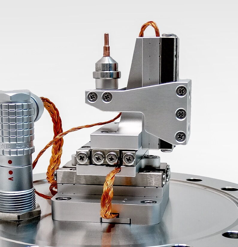
Image: SmarAct
UHV service demands more rigorous material selection. The PZT-to-stator bond must use a UHV-compatible adhesive (e.g., Epo-Tek H77 or similar, or solder bonding for the most demanding applications). All metals must be vacuum-cleaned and baked at 150 to 200 °C. Wiring uses bare or Kapton-insulated conductors with spot-welded or crimped connections, avoiding solder flux residue. Feedthroughs are typically ceramic-to-metal brazed connectors.
Properly designed UHV piezo stages achieve base pressures below 5 × 10⁻¹⁰ Pa and are routinely used in surface science, STM/AFM instruments, and synchrotron beamline optics.
EUV lithography environments
EUV (13.5 nm wavelength) lithography operates in near-UHV conditions with additional constraints on hydrocarbon contamination. Even trace hydrocarbons can deposit carbon on EUV optics, degrading reflectivity. Piezo motors are attractive here because they eliminate both magnetic interference (which affects the electron-beam source) and the hydrocarbon contamination risk from lubricants.
The particle generation concern is managed by enclosing the friction zone and placing the motor assembly behind baffles, away from the optical path. Several EUV tool manufacturers use piezo-driven stages for reticle alignment, mirror tilting, and fine focus adjustment.
Cryogenic vacuum environments
Some applications combine vacuum with cryogenic temperatures (4 K to 77 K). Piezo ceramics retain their piezoelectric properties at cryogenic temperatures, although the piezoelectric coefficients (d₃₁, d₃₃) decrease by 30 to 60% at 4 K compared to room temperature values. The resonant frequency of the stator shifts upward as the material stiffens. These changes are predictable and can be compensated in the drive electronics.
Electromagnetic motors, by contrast, face challenges with superconducting shorts in wiring insulation at very low temperatures, and NdFeB magnets actually improve in performance at cryogenic temperatures, which is one area where they hold an advantage.
Space and radiation environments
Space applications combine vacuum with radiation exposure, thermal cycling, and launch vibration. Piezo motors are well suited to the vacuum aspect, but the radiation environment introduces additional considerations.
PZT ceramics are inherently radiation-tolerant. The piezoelectric effect is a bulk crystallographic property that is not affected by ionizing radiation at doses below approximately 10⁸ rad (Si). For comparison, low-Earth orbit missions accumulate 10 to 100 krad over 10 to 15 years. The PZT itself is effectively immune to radiation damage for all practical space missions.
The vulnerable components are the drive electronics (which are typically located outside the vacuum and shielded) and any organic materials in the motor assembly. Epoxy adhesives can become brittle after doses above 10⁷ rad; Kapton insulation tolerates 10⁹ rad. For high-radiation environments (Jupiter missions, nuclear reactor instrumentation), all-inorganic construction (solder bonds, ceramic bead insulation, spot-welded connections) provides the necessary radiation hardness.
Outgassing behaviour changes in the space environment. Molecular contaminants outgassed from a spacecraft component can condense on nearby cold surfaces (such as telescope mirrors or radiator panels), degrading optical performance or thermal control. The ASTM E595 screening test was developed specifically for this scenario. Piezo motors using qualified materials (TML < 1.0%, CVCM < 0.1%) routinely pass spacecraft material reviews.
Piezo motors have flown on numerous space missions, including the Mars rovers (sample handling mechanisms), the Herschel Space Observatory (grating positioning), and various satellite optical instruments. Their combination of vacuum compatibility, low power consumption, zero magnetic emission, and self-locking (holding position without power) makes them attractive for space mechanisms where reliability over multi-year missions is paramount.
Accelerator and fusion research environments
Particle accelerators and fusion reactors present unique vacuum challenges: extremely low base pressures (10⁻¹⁰ to 10⁻¹² Pa for storage rings), high radiation fields near the beamline, and the need for remote alignment of optical and magnetic components. Piezo motors are widely used in synchrotron beamlines for mirror, monochromator, and slit positioning.
The key requirement in accelerator environments is bakeability. The entire beamline vacuum system, including all in-vacuum motors and stages, must survive bakeout at 150 to 250 °C. Standard piezo motors with epoxy bonds (rated to 150 to 200 °C) satisfy most beamline requirements. For locations near the interaction point of a collider or inside a bending magnet, solder-bonded stators with all-inorganic construction are specified.
Radiation damage near the beamline is highly localized. Motors positioned behind shielding (as most positioning motors are) receive modest doses. In locations with direct beam exposure, the radiation tolerance of PZT ceramics (10⁸ rad) provides far more margin than the organic components, reinforcing the importance of all-inorganic construction for the most demanding installations.
Practical design considerations for vacuum piezo stages
Feedthrough design
The electrical connection from the external drive electronics to the in-vacuum motor passes through a vacuum feedthrough. Piezo motors typically require only two to four electrical connections (one or two drive phases plus ground), carrying AC signals at 20 to 200 kHz with peak voltages of 100 to 200 V and currents below 1 A. Standard ceramic-sealed BNC or SMA feedthroughs are adequate. This is far simpler than the multi-conductor feedthroughs required for stepper motors (4 to 8 wires) or brushless DC motors (3 phases plus Hall sensors, 6 to 9 wires).
Thermal management
Although piezo motors are more efficient than electromagnetic motors in terms of heat generation per unit force, they still produce heat, primarily in the PZT elements (dielectric losses) and at the friction interface. In vacuum, this heat must be conducted away through the mounting structure. Design rules of thumb include:
- Mount the motor stator on a thermally conductive base (aluminum or copper) with good thermal contact to the chamber wall or optical table.
- For high-duty-cycle applications, calculate the thermal resistance from stator to heat sink and verify that the stator temperature stays below the Curie temperature limit (see the companion article on thermal behaviour).
- Flexible copper braids can provide supplemental thermal paths without introducing mechanical distortion.
Position sensing
Encoder readheads and scales used in vacuum stages must also meet outgassing and particle requirements. Optical encoders (glass scales with chrome gratings) are well-suited to vacuum; capacitive encoders (with PCB-based scales) are also common. Magnetic encoders are generally avoided in applications sensitive to stray fields, which are exactly the applications where piezo motors are preferred.
Cable management
Cables inside vacuum chambers must use low-outgassing insulation (Kapton, PTFE, or bare wire with ceramic bead insulators for UHV). Cable routing must minimize flexure at the point of motion to avoid particle generation from insulation abrasion. Flat flex cables with Kapton insulation are commonly used in HV; ceramic-beaded wires or spot-welded ribbon cables are used in UHV.
Cleanroom classification and motor compatibility
Cleanroom operation adds a distinct set of requirements beyond vacuum. The ISO 14644-1 classification defines maximum particle concentrations at each cleanliness level:
| ISO Class | Max particles ≥ 0.1 µm per m³ | Max particles ≥ 0.5 µm per m³ | Typical application |
|---|---|---|---|
| ISO 1 | 10 | N/A | Extreme EUV lithography |
| ISO 2 | 100 | N/A | Advanced lithography |
| ISO 3 | 1,000 | 35 | Wafer processing |
| ISO 4 | 10,000 | 352 | Semiconductor front-end |
| ISO 5 | 100,000 | 3,520 | Assembly, inspection |
| ISO 6 | 1,000,000 | 35,200 | Optics, disk drive |
| ISO 7 | N/A | 352,000 | General cleanroom |
For piezo motors in cleanroom service, the primary concern is particles generated at the friction interface. The motor itself does not generate airborne molecular contamination (AMC) in the way that lubricant-based systems do, but wear particles can become airborne if not contained.
Cleanroom qualification testing
Qualifying a piezo stage for cleanroom use follows a standard protocol:
-
Baseline measurement. Place the stage in a mini-environment with particle counters (0.1 µm and 0.5 µm channels) and run the counters for 30 minutes with the stage stationary. This establishes the background count.
-
Operational measurement. Run the stage through its intended motion profile (velocity, acceleration, duty cycle) while continuously monitoring particle counts. The difference between operational and baseline counts is the stage's particle contribution.
-
Sustained operation. Continue the motion profile for 8 to 24 hours. Particle generation from new stages is typically higher in the first 1,000 to 10,000 cycles ("running-in" period) and then drops to a steady-state rate.
-
Post-test inspection. Examine the friction interface and surrounding areas under a microscope. Document wear patterns and particle accumulation zones.
Typical results for well-designed piezo stages: ISO Class 3 operation (< 1,000 particles ≥ 0.1 µm per m³) is achievable with enclosed friction zones. ISO Class 1 requires additional measures such as dedicated exhaust near the friction zone and HEPA-filtered mini-environments around the stage.
Bakeout protocols for vacuum service
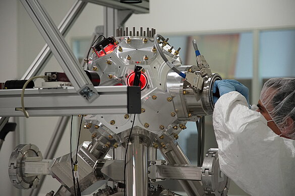
Image: Physik Instrumente (PI)
Bakeout is the process of heating a vacuum component to drive off adsorbed gases and reduce outgassing. For piezo stages, the bakeout must be gentle enough to avoid damaging the PZT ceramic, adhesive bonds, and encoder components.
Standard HV bakeout (10⁻⁶ Pa target):
- Temperature: 80 to 100 °C
- Duration: 24 hours minimum
- Ramp rate: < 2 °C per minute to avoid thermal shock to PZT bonds
- Atmosphere during bakeout: dry nitrogen purge until vacuum system is ready
UHV bakeout (10⁻⁹ Pa target):
- Temperature: 120 to 150 °C (limited by adhesive bond thermal rating)
- Duration: 48 to 72 hours
- Ramp rate: < 1 °C per minute
- Multiple cycles may be needed: bake, pump down, measure base pressure, repeat if needed
Components that limit bakeout temperature:
- Epoxy adhesive bonds (PZT to stator): typically rated to 150 to 200 °C. Solder bonds allow higher temperatures (up to 300 °C for Sn-Ag solders).
- Encoder readheads: glass-scale optical encoders tolerate 150 °C. Some capacitive encoders with PCB elements are limited to 100 °C.
- Wiring insulation: Kapton is rated to 400 °C. PTFE to 260 °C. PVC must never be used in vacuum bakeout.
- Preload springs: beryllium copper maintains spring properties to 200 °C. Stainless steel is stable to 300 °C.
Comparison summary
| Parameter | Electromagnetic motor | Piezo motor |
|---|---|---|
| Outgassing (after bakeout) | 10⁻⁷ to 10⁻⁸ Pa·m/s | 10⁻⁹ to 10⁻¹⁰ Pa·m/s |
| Stray magnetic field at 50 mm | 0.5 to 5 mT | < 1 nT |
| Particle generation source | Bearings, brushes, magnets | Friction interface |
| Lubricant requirement | Yes (bearings, gearbox) | No |
| Minimum vacuum level (standard) | 10⁻⁶ Pa (with modification) | 10⁻⁶ Pa (minimal modification) |
| UHV compatible | With extensive redesign | With moderate redesign |
| Cryogenic operation | Possible (with caveats) | Possible (reduced d₃₃) |
| Heat generation in vacuum | High (I²R in coils) | Low to moderate |
| Drive feedthrough complexity | 6 to 12 conductors | 2 to 4 conductors |
Material screening and outgassing qualification
Before any component enters a vacuum system, it must be screened for outgassing. The standard test methods, ASTM E595 and ECSS-Q-ST-70-02, measure total mass loss (TML) and collected volatile condensable material (CVCM) after 24 hours at 125 °C and 10⁻⁵ Pa. For piezo motor components, the critical materials and their typical outgassing properties are:
| Material | TML (%) | CVCM (%) | Status |
|---|---|---|---|
| PZT ceramic (sintered) | < 0.01 | < 0.01 | Inherently clean |
| Stainless steel (cleaned) | < 0.01 | < 0.01 | Inherently clean |
| Phosphor bronze (cleaned) | < 0.01 | < 0.01 | Inherently clean |
| Epo-Tek H77 adhesive (cured) | 0.68 | 0.01 | Acceptable |
| Kapton polyimide | 1.09 | 0.02 | Acceptable |
| PTFE (virgin) | 0.01 | 0.01 | Excellent |
| Standard PVC insulation | 1.5 to 3.0 | 0.5 to 1.5 | Unacceptable |
| Nylon (PA6) | 2.5 to 4.0 | 0.2 to 0.8 | Unacceptable |
Materials with TML below 1.0% and CVCM below 0.1% are generally acceptable for HV service. For UHV, stricter criteria apply: CVCM below 0.01% and total outgassing rate below 10⁻⁹ Pa·L/(s·cm²) after bakeout.
Residual gas analysis for contamination monitoring
Residual gas analysis (RGA) using a quadrupole mass spectrometer is the definitive tool for verifying that a piezo stage meets outgassing requirements in situ. The RGA identifies specific contaminants by their mass-to-charge ratio:
- Mass 18 (water): the dominant residual gas in most systems. A well-baked system shows water at 10⁻⁸ to 10⁻⁹ Pa.
- Mass 28 (nitrogen/CO): indicates a leak (nitrogen) or residual carbon monoxide from bakeout.
- Mass 44 (CO₂): present during initial pumpdown and bakeout, decreasing over time.
- Masses 39-41, 55-57 (hydrocarbons): indicators of organic contamination from adhesives, insulation, or fingerprints. These must be absent (below the RGA detection limit) for UHV and EUV applications.
- Mass 69 (CF₃⁺): indicates fluoropolymer degradation if PTFE is overheated during bakeout.
The RGA is run continuously during the first bakeout cycle to verify that no unexpected contaminants are evolving. After the system reaches base pressure, a final RGA scan serves as the acceptance record. Any hydrocarbon peaks above 10⁻¹⁰ Pa require investigation and remediation before the system is released for use.
Material substitution for extreme vacuum
For applications below 10⁻⁹ Pa (XHV, extreme high vacuum), organic materials are progressively eliminated:
- Epoxy adhesive bonds are replaced with active metal braze or solder bonds (indium-tin or gold-tin). These bonds withstand bakeout temperatures above 300 °C and contribute zero organic outgassing.
- Kapton-insulated wires are replaced with bare wire threaded through alumina ceramic beads. Connections are made by spot-welding rather than soldering (solder flux is a persistent contaminant source).
- Encoder readheads using organic adhesives are replaced with mechanically clamped or brazed assemblies.
These substitutions increase cost and assembly complexity but enable piezo motors to operate in environments down to 10⁻¹¹ Pa, such as particle accelerator beamlines and gravitational wave detector vacuum systems.
When electromagnetic motors still win
Piezo motors are not universally superior in vacuum. Electromagnetic motors retain advantages in:
- High-speed continuous rotation. Ultrasonic rotary motors are limited to roughly 200 rpm for most designs. Brushless DC motors can deliver tens of thousands of rpm.
- High continuous force/torque. Electromagnetic motors can sustain peak force indefinitely (limited by thermal rise). Piezo motors experience accelerated wear under continuous high-load operation.
- Long travel at high speed. For stages requiring hundreds of millimetres of travel at velocities above 100 mm/s, electromagnetic linear motors (ironless voice coils, linear brushless) are more practical.
- Cost. Vacuum-compatible electromagnetic motors are available from many suppliers at moderate cost. Vacuum-qualified piezo stages remain a specialty product with higher unit prices.
The decision matrix in practice: if the application requires low stray magnetic fields, UHV compatibility, or particle-sensitive operation at moderate speeds and forces, piezo motors are the clear choice. If the application demands high speed, high continuous force, or low cost at HV levels, electromagnetic motors may be more practical.
Worked example: specifying a vacuum piezo stage
Consider a synchrotron beamline mirror adjustment stage with the following requirements:
- Vacuum level: 5 × 10⁻⁹ Pa (UHV)
- Travel: 10 mm linear, 2 mrad tilt
- Resolution: 50 nm linear, 0.1 µrad angular
- Stray magnetic field: < 100 nT at 100 mm
- Particle budget: ISO Class 3 equivalent at the mirror surface
- Duty cycle: < 5% (intermittent adjustment, not continuous scanning)
Motor selection: A standing-wave ultrasonic linear motor with alumina friction tip and silicon nitride runner satisfies the magnetic field requirement with no shielding. The low duty cycle means wear-related particle generation is minimal over the instrument's lifetime.
Material choices: Stator body in titanium grade 5 (low outgassing, non-magnetic, good thermal conductivity). PZT bonded with Epo-Tek H77 adhesive, baked at 150 °C for 48 hours. Electrical connections via Kapton-insulated wire, spot-welded to PZT electrodes.
Bearing system: Flexure-based (no rolling elements), providing zero particle generation and no lubricant requirement.
Feedthrough: Two SMA feedthroughs (one per drive phase), rated to 10⁻¹⁰ Pa·m/s leak rate.
Position feedback: Optical linear encoder with glass scale, qualified for UHV. Separate capacitive sensors for angular readout.
Estimated outgassing contribution: < 2 × 10⁻¹⁰ Pa·m/s for the complete stage assembly, compatible with the 5 × 10⁻⁹ Pa system requirement with substantial margin.
This type of stage is commercially available from several manufacturers and represents a straightforward application of piezo technology in vacuum. The total cost is typically 2 to 4 times that of an equivalent electromagnetic stage, justified by the elimination of magnetic shielding, the simplified feedthrough, and the inherent cleanliness of the drive mechanism.
Cost-benefit analysis for vacuum motor selection
The higher unit price of vacuum-qualified piezo stages often misleads initial cost comparisons. A more complete analysis considers total cost of ownership:
- Magnetic shielding (avoided). A mu-metal shield for an electromagnetic motor adds $500 to $5,000 depending on size and attenuation requirements.
- Feedthrough complexity (reduced). A 2-pin piezo feedthrough costs $200 to $500. A 9-pin feedthrough for a brushless DC motor with Hall sensors costs $800 to $2,000 for UHV-rated connectors.
- Thermal management (simplified). Piezo motors dissipate 5 to 20x less heat than equivalent electromagnetic motors, reducing or eliminating the need for liquid cooling or thermal straps inside vacuum.
- Maintenance and requalification. Electromagnetic motors in vacuum require periodic lubricant replenishment (for bearing-supported types) or bearing replacement. Each maintenance cycle requires venting, bakeout, and requalification: a process costing $2,000 to $10,000 in downtime and labour. Piezo motors with flexure bearings require no lubrication and have no maintenance schedule.
- System integration time. Eliminating magnetic shielding design, thermal management analysis, and complex feedthrough wiring reduces system integration effort by 20 to 40 engineering hours per axis.
For systems with 3 or more motion axes in vacuum, the total cost of ownership often favours piezo motors despite higher unit prices. For single-axis applications at moderate vacuum levels (HV), the cost advantage may favour electromagnetic motors.
Summary
Ultrasonic piezoelectric motors are inherently better suited to vacuum and cleanroom environments than electromagnetic alternatives. Their zero magnetic emission, low outgassing, and lubricant-free operation address the three primary contamination concerns in these environments. The one area requiring careful attention, particle generation from the friction interface, is manageable through design measures that are well understood and widely implemented. For applications in semiconductor processing, electron microscopy, synchrotron science, and space instrumentation, piezo motors have become the standard solution for precision motion in contamination-sensitive environments.