Fundamentals
Thermal behaviour of piezo actuators: the 60°C stator shift problem
Resonant frequency drift, Curie temperature limits, and thermal management for reliable operation
Every ultrasonic piezo motor is a resonant device. It operates at a specific mechanical resonance frequency, typically between 20 kHz and 200 kHz, where the stator vibration amplitude peaks and the motor produces useful force and velocity. That resonant frequency is not fixed. It shifts with temperature, and the shift is large enough to take the motor out of its operating band if the drive electronics cannot track it. This is the 60 °C stator shift problem: at roughly 60 °C above ambient, many PZT-based stators have shifted their resonant frequency by 1 to 3%, enough to halve the motor's force output or stall it entirely. Understanding and managing this behaviour is essential for any piezo motor application that operates outside a narrow temperature window.
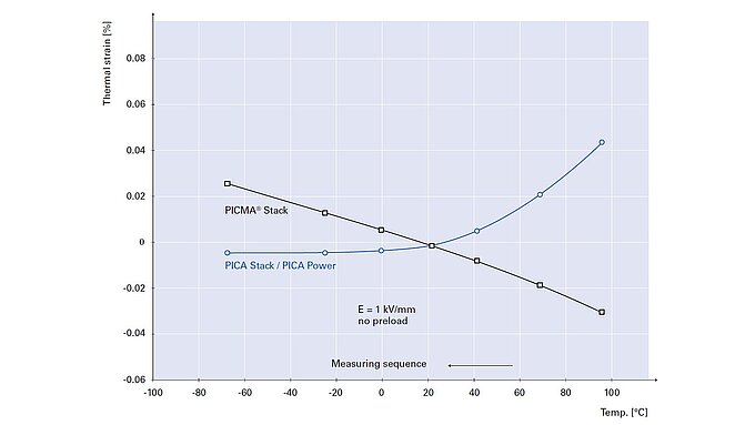
Image: Physik Instrumente (PI)
Why resonant frequency changes with temperature
The resonant frequency of a vibrating stator depends on its geometry, mass, and elastic stiffness. For a simplified beam-type stator, the fundamental frequency scales as:
f ∝ √(E / ρ) × (t / L²)
where E is the effective Young's modulus, ρ is the density, t is the thickness, and L is the length. Temperature affects both E and ρ (through thermal expansion), but the dominant effect is the change in the elastic constants of the PZT ceramic.
The softening of PZT with temperature
PZT (lead zirconate titanate) is a ferroelectric material. Its elastic, dielectric, and piezoelectric properties are all temperature-dependent, and the dependencies are not linear. As temperature increases from room temperature toward the Curie temperature:
- The elastic compliance (s₁₁, s₃₃) increases, meaning the material becomes softer.
- The piezoelectric coefficients (d₃₁, d₃₃) increase, meaning the material becomes more responsive to applied voltage.
- The dielectric permittivity (ε₃₃) increases, meaning the material draws more current at a given voltage and frequency.
- The mechanical quality factor (Qm) decreases, meaning losses increase and the resonance peak broadens.
The net effect on resonant frequency is a downward shift. For common "hard" PZT compositions (PZT-4, PZT-8, and their commercial equivalents), the resonant frequency decreases by approximately 0.02 to 0.05% per degree Celsius. This sounds small, but it accumulates:
| Temperature rise (°C) | Frequency shift (%) | Shift for 40 kHz stator (Hz) |
|---|---|---|
| 10 | 0.2 to 0.5 | 80 to 200 |
| 30 | 0.6 to 1.5 | 240 to 600 |
| 60 | 1.2 to 3.0 | 480 to 1200 |
| 100 | 2.0 to 5.0 | 800 to 2000 |
A 40 kHz motor with a mechanical Q of 500 has a 3 dB bandwidth of only 80 Hz. A frequency shift of 500 Hz moves the operating point completely off the resonance peak, reducing vibration amplitude by an order of magnitude. The motor effectively stops working.
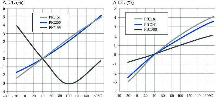
Image: Resonant frequency shift (Δfs/fs) as a function of temperature for PI PIC-series hard and soft PZT ceramics, illustrating the non-linear drift that drives electronics must compensate. Source: Physik Instrumente (PI)
Contributions from the metal stator body
The PZT ceramic is bonded to a metal stator body (typically stainless steel, phosphor bronze, or titanium). The metal's elastic modulus also decreases with temperature, but by a smaller fraction: roughly 0.02 to 0.04% per degree Celsius for stainless steel. Since the stator is a composite structure, the overall frequency shift is a weighted average of the PZT and metal contributions. In practice, the PZT dominates because its temperature coefficients are 2 to 5 times larger than those of the metal.
Thermal expansion of the stator body changes its dimensions and therefore its resonant frequency. For stainless steel with a CTE of 16 × 10⁻⁶ /°C, a 60 °C rise changes the length by roughly 0.1%. This contributes a frequency shift of approximately 0.05%, small compared to the PZT stiffness change, but not negligible.
Transient thermal analysis: time constants and thermal modeling
Understanding the transient thermal response of a piezo motor is essential for predicting how quickly the stator heats up after power is applied and how long it takes to cool down after the drive is turned off. The thermal behaviour follows an exponential model governed by the thermal time constant τ = R_th × C_th, where R_th is the thermal resistance from the PZT to the heat sink (°C/W) and C_th is the thermal capacitance of the stator assembly (J/°C).
Lumped-parameter thermal model
For a typical miniature piezo motor stator (mass 5 to 15 g), the thermal system can be modelled as a single lumped mass connected to the mounting base through a thermal resistance. The key parameters are:
- Thermal mass of the stator: C_th = m × c_p. For a 10 g stainless steel stator, C_th = 0.010 kg × 500 J/(kg·°C) = 5 J/°C.
- Thermal resistance from stator to mount: this depends on the contact area, interface material, and mounting method. Typical values range from 5 to 50 °C/W for bolted connections (lower values with thermal grease, higher values with point contact or ceramic spacers).
- Thermal time constant: for C_th = 5 J/°C and R_th = 20 °C/W, τ = 100 seconds.
The stator temperature rise follows T(t) = P × R_th × (1 - e^(-t/τ)), where P is the dissipated power. For P = 0.5 W and the values above, the steady-state temperature rise is 10 °C, reached (to 95%) in approximately 5τ = 500 seconds (about 8 minutes).
Multi-node models for precision applications
The single-node model is adequate for estimating peak stator temperature but insufficient for predicting thermal gradients within the stator. Temperature gradients matter because they cause non-uniform expansion, which distorts the vibration mode shape and degrades motor efficiency.
A two-node model separates the PZT ceramic from the metal stator body. The PZT (where most dielectric loss occurs) heats first, and heat then conducts through the adhesive bond layer to the metal body. The adhesive layer, typically 10 to 50 µm of epoxy with thermal conductivity of 0.2 to 1 W/(m·K), creates a thermal bottleneck. For a 10 × 10 mm bond area with 20 µm thickness and k = 0.5 W/(m·K), the thermal resistance of the bond layer is:
R_bond = thickness / (k × area) = 0.00002 / (0.5 × 0.0001) = 0.4 °C/W
This is small compared to the stator-to-mount resistance but becomes significant for stators with large PZT volumes and high duty cycles, where internal temperature gradients of 5 to 15 °C between the PZT core and the stator surface can develop.
Finite element thermal simulation
For critical applications, finite element analysis (FEA) provides the most accurate thermal predictions. The simulation requires:
- Volumetric heat generation in the PZT (calculated from the dielectric loss: P = 2π × f × ε₃₃ × tan δ × E² × volume, where f is frequency, E is the electric field, and tan δ is the loss tangent).
- Frictional heat generation at the contact tip (calculated from friction force × sliding velocity).
- Boundary conditions: conduction to mount (with contact resistance), radiation to surroundings (significant in vacuum), and convection if in atmosphere.
- Temperature-dependent material properties (the loss tangent of PZT increases with temperature, creating a positive feedback loop that can cause thermal runaway if not managed).
The FEA approach is particularly important for motors operating near their thermal limits or in vacuum, where the absence of convective cooling concentrates heat in the stator and creates steep thermal gradients.
The Curie temperature ceiling
Every ferroelectric material has a Curie temperature (Tc) above which it loses its piezoelectric properties permanently. The ceramic undergoes a phase transition from the ferroelectric (tetragonal or rhombohedral) phase to the paraelectric (cubic) phase, and the spontaneous polarization vanishes. For common PZT compositions:
| Material | Curie temperature (°C) |
|---|---|
| PZT-4 (hard) | 328 |
| PZT-5A (soft) | 365 |
| PZT-8 (hard) | 300 |
| PZT-5H (soft) | 193 |
| Lithium niobate | 1150 |
| BaTiO₃ | 120 |
For ultrasonic motors, hard PZT compositions (PZT-4, PZT-8) are preferred because of their high mechanical quality factor, which enables large vibration amplitudes at resonance. Their Curie temperatures of 300 to 330 °C provide substantial margin above normal operating temperatures.
However, the usable temperature limit is well below Tc. As the temperature approaches Tc, the piezoelectric coefficients become unstable, hysteresis increases, and aging accelerates. A practical rule is to limit the maximum PZT temperature to Tc minus 100 °C for standard operation, or Tc minus 50 °C as an absolute upper bound. For PZT-8 (Tc = 300 °C), this means a maximum recommended operating temperature of approximately 200 °C. For PZT-5H (Tc = 193 °C), the limit drops to roughly 100 °C, which is uncomfortably close to the temperatures reached during high-duty-cycle operation.
Depolarization below Curie temperature
Partial depolarization can occur at temperatures significantly below Tc, especially under sustained mechanical stress or strong AC electric fields. This is a concern for ultrasonic motors because the PZT operates simultaneously under high AC drive (10 to 200 V peak, at resonance) and mechanical stress from the preload force. Combined thermo-electro-mechanical loading can cause domain reorientation that partially depolarizes the ceramic over time. The depolarization is not instantaneous; it manifests as a gradual loss of motor performance over thousands of hours.
The practical implication: a motor that works fine at 80 °C during a short test may exhibit measurably degraded performance after 1000 hours at the same temperature due to cumulative partial depolarization.
Image: Physik Instrumente (PI)
Thermal expansion and its effect on positioning
Stator dimensional changes
Thermal expansion of the stator directly affects the contact geometry between the friction tip and the runner. As the stator expands, the preload changes, which affects both force output and friction-interface wear. For a stator with 10 mm between the mounting point and the friction tip, a 60 °C temperature rise causes:
- Stainless steel: 10 mm × 16 × 10⁻⁶ /°C × 60 °C = 9.6 µm
- Titanium: 10 mm × 8.6 × 10⁻⁶ /°C × 60 °C = 5.2 µm
- Invar: 10 mm × 1.2 × 10⁻⁶ /°C × 60 °C = 0.7 µm
A 10 µm change in the preload gap translates directly to a change in preload spring deflection. If the preload spring has a rate of 5 N/mm, this is a 0.05 N change, which can be significant for miniature motors with nominal preloads of 0.5 to 2 N.
Stage-level thermal drift
Positioning accuracy is often limited not by the motor itself but by thermal expansion of the stage structure. An aluminium stage base 200 mm long expands by 200 × 23 × 10⁻⁶ × 1 °C = 4.6 µm per degree Celsius. For nanometre-level positioning, even fractional-degree temperature changes are significant.
This problem is common to all motor technologies, not unique to piezo. But it interacts with piezo-specific effects in two ways:
- The motor's self-heating contributes to stage thermal drift. A piezo motor dissipating 0.5 W in a thermally isolated stage can raise the stage temperature by several degrees.
- The motor's resonant frequency shift due to self-heating can cause the drive electronics to compensate by changing drive amplitude or frequency, which alters the motor's heat dissipation, creating a feedback loop.
The 60 °C problem in practice
The "60 °C stator shift problem" refers specifically to the scenario where a motor, designed and tuned for room-temperature operation, is deployed in an environment 60 °C warmer (or heats itself to 60 °C above ambient during operation). At this temperature rise, the combination of resonant frequency shift, reduced Qm, and preload change can reduce motor performance by 30 to 70%.
Case study: semiconductor wafer handling
A piezo linear motor driving a wafer transfer arm operates in a process module at 80 °C ambient (room temperature plus process heating). The motor was characterized at 25 °C, where it achieved 5 N force at 50 mm/s. At 80 °C (ΔT = 55 °C):
- Resonant frequency dropped by 1.8% (from 42.0 kHz to 41.24 kHz).
- The drive electronics, using a fixed-frequency oscillator, were still driving at 42.0 kHz.
- Vibration amplitude dropped to 35% of its room-temperature value.
- Motor force dropped to approximately 1.8 N, insufficient for reliable wafer transport.
- The solution: replacing the fixed-frequency driver with a phase-locked loop (PLL) that tracks the resonant frequency automatically.
This case illustrates why frequency tracking is not optional for any application with temperature variation greater than 10 to 15 °C.
Case study: optical fiber alignment in a telecommunications module
A 6-axis piezo positioning stage aligns a single-mode fiber to a photonic chip inside a hermetically sealed package. The package undergoes reflow soldering at 260 °C (briefly) and then operates in a telecom enclosure at 55 °C ambient. During alignment (before sealing), the stage operates at room temperature and achieves coupling efficiency above 90%. After the package is sealed and powered in the enclosure, the fibre-to-chip alignment must remain within ±100 nm over the operating temperature range of 0 to 70 °C.
The piezo stage itself is outside the sealed package, but the optical bench carrying the fiber expands with temperature. The stage compensates by adjusting position based on a temperature sensor reading. The critical insight: the motor's own thermal drift (resonant frequency shift, preload change) must not consume any of the ±100 nm error budget allocated to thermal compensation. With a PLL-tracked drive and a thermally decoupled mounting, the motor's contribution to positioning error stays below 5 nm over the full temperature range, leaving 95 nm of budget for the optical bench expansion correction.
This application demonstrates how thermal management of the piezo motor enables thermal compensation of the larger system. If the motor itself introduced 50 nm of thermal drift, the available budget for bench compensation would shrink to 50 nm, requiring a 2x tighter thermal model or active cooling of the optical bench.
Drive electronics: frequency tracking strategies
Phase-locked loop (PLL)
The most common approach uses a PLL to lock the drive frequency to the motor's resonant frequency. The PLL monitors the phase relationship between the drive voltage and the motor current. At resonance, the phase difference is near zero (for a series resonance) or reaches a characteristic value (for a parallel resonance). The PLL adjusts the drive frequency to maintain this phase relationship as the resonant frequency drifts.
PLL tracking works well for slow temperature changes (minutes to hours). It can track frequency shifts of several percent, more than sufficient for thermal drift. The main limitation is that the PLL can lose lock during rapid temperature transients or if the Q factor drops so low that the phase transition at resonance becomes too gradual to detect reliably.
Typical PLL tracking bandwidth: 100 to 1000 Hz update rate, capable of following resonant frequency changes of up to 100 Hz/s.
Admittance (impedance) tracking
An alternative approach measures the electrical admittance of the motor at multiple frequencies and identifies the resonant peak directly. This is more robust than PLL in low-Q conditions but requires a more complex excitation scheme (frequency sweeps or multi-tone excitation). It is used in high-reliability applications where PLL lock loss is unacceptable.
Digital frequency scanning
Modern digital drive electronics can periodically sweep the drive frequency across a window around the expected resonance, measure the motor response (vibration amplitude, current draw, or velocity), and adjust the operating frequency to the optimum point. This approach is robust and flexible but introduces brief interruptions in motor operation during the sweep. For intermittent positioning applications, this is acceptable; for continuous scanning, it is not.
Temperature feedforward
If the stator temperature is measured (by an embedded thermocouple or thermistor, or inferred from the drive current), the expected frequency shift can be predicted from the known temperature coefficient and applied as a feedforward correction to the drive frequency. This reduces the burden on the PLL or impedance tracker and improves transient response. The temperature coefficient must be calibrated for each motor design, as it depends on the PZT composition, stator geometry, and bonding method.
Thermal management strategies
Reducing heat generation
The primary heat sources in an ultrasonic piezo motor are:
- Dielectric losses in PZT. The PZT dissipates power proportional to the square of the drive voltage, the frequency, and the loss tangent (tan δ). For hard PZT at 40 kHz and 100 V peak, typical dissipation is 0.1 to 1 W.
- Friction at the contact interface. The sliding contact between the stator tip and runner generates frictional heat proportional to the normal force, sliding velocity, and friction coefficient. This can be 0.1 to 0.5 W during active motion.
- Structural damping. Internal friction in adhesive layers, bolted joints, and other structural elements contributes a smaller amount.
Strategies to reduce heat generation:
- Minimize drive voltage. Operate at the lowest voltage that provides adequate force. Dielectric losses scale with V².
- Use hard PZT. PZT-8 has a loss tangent roughly half that of PZT-4 and one-fifth that of PZT-5A.
- Reduce duty cycle. If the application permits, move the motor quickly and then hold position with the power off (the motor's self-locking property provides holding force without power).
- Operate in burst mode. For positioning applications, apply drive power only during moves, then rely on the motor's self-locking friction to hold position. A motor that runs at 50% duty cycle with 1 W peak dissipation produces an average heat load of 0.5 W. Reducing the duty cycle to 10% (short, rapid moves with long hold periods) drops the average to 0.1 W, which most stators can dissipate with minimal temperature rise.
- Optimize preload. Excessive preload increases frictional heating without proportionally increasing useful force.
Removing heat
- Conductive paths. Mount the stator on a thermally conductive base with good contact (thermal grease or indium foil interface in vacuum). Aluminium and copper brackets can conduct heat to a heat sink or the machine frame.
- Forced air cooling (in atmospheric applications). Even low-velocity airflow dramatically reduces stator temperature rise. A small fan delivering 1 m/s airflow can reduce the temperature rise by 50 to 70%.
- Thermal straps (in vacuum applications). Flexible copper braids or straps connect the motor mount to a temperature-controlled surface.
- Peltier coolers. For precision applications where stator temperature must be held within 1 to 2 °C, a thermoelectric cooler can actively regulate the motor temperature. This adds complexity and power consumption but eliminates thermal drift.
Design for thermal stability
- Symmetric stator design. A thermally symmetric stator expands uniformly, maintaining the mode shape even as the dimensions change. Asymmetric heating causes mode distortion that reduces motor efficiency beyond what frequency shift alone would predict.
- Invar or titanium stator bodies. Low-CTE materials reduce dimensional changes and preload shifts. Titanium (CTE = 8.6 × 10⁻⁶ /°C) is roughly half the expansion of stainless steel.
- Temperature-compensated preload. A preload mechanism designed so that thermal expansion of the motor is offset by expansion of the preload spring mount can maintain constant preload over a temperature range. This requires careful mechanical design and material selection.
- Thermally decoupled mounting. Isolating the motor from the stage structure with low-conductivity spacers (e.g., ceramic washers) prevents motor self-heating from affecting the stage's positional stability. The tradeoff is that the motor itself runs hotter.
Temperature ranges for different PZT compositions
The choice of PZT composition determines the usable temperature range:
Standard hard PZT (PZT-4, PZT-8): -40 °C to +200 °C
Suitable for the vast majority of industrial and scientific applications. Performance degrades gracefully with temperature; no cliff-edge failure below 200 °C. Resonant frequency tracking is required above ΔT = 15 °C from the calibration temperature.
Soft PZT (PZT-5A, PZT-5H): -40 °C to +80 °C
Soft compositions are rarely used in ultrasonic motors because of their low Qm, but they appear in some sensor and actuator hybrid designs. Their lower Curie temperatures and higher temperature sensitivity make them unsuitable for elevated-temperature service.
High-temperature compositions: up to 300 °C
Bismuth titanate (Bi₄Ti₃O₁₂), modified PZT with manganese or antimony doping, and other specialized compositions can operate at higher temperatures. These are used in downhole oil and gas applications, jet engine monitoring, and nuclear instrumentation. Their piezoelectric coefficients are lower than standard PZT, so motor force and velocity are reduced.
Cryogenic operation: down to 4 K
PZT retains piezoelectric activity at cryogenic temperatures, but the coefficients decrease significantly. At 77 K (liquid nitrogen), d₃₃ is typically 60 to 70% of the room-temperature value. At 4 K (liquid helium), it drops to 40 to 50%. The resonant frequency increases by 2 to 4% due to stiffening of the ceramic. These changes are predictable and can be compensated, making cryogenic piezo motors practical for applications in cryostats, dilution refrigerators, and space instruments.
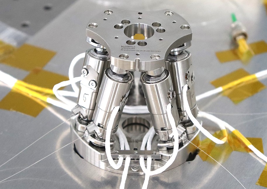
Image: A PI cryogenic hexapod for quantum technology applications, demonstrating piezo-actuated precision positioning at temperatures down to 4 K. The six piezoelectric legs deliver sub-micron positioning accuracy even at liquid-helium temperatures where d₃₃ drops to 40 to 50% of the room-temperature value. Source: Physik Instrumente (PI)
Worked example: predicting stator frequency shift
A Langevin-type ultrasonic motor has a room-temperature resonant frequency of 40.00 kHz. The stator uses PZT-8 ceramics bonded to a stainless steel body. The temperature coefficient of resonant frequency has been measured at -0.03%/°C.
Problem: The motor will operate in an enclosure where ambient temperature varies from 20 °C to 50 °C. During operation, stator self-heating adds another 15 °C. What frequency tracking range must the drive electronics support?
Solution:
- Minimum stator temperature: 20 °C (ambient, motor off)
- Maximum stator temperature: 50 + 15 = 65 °C (worst-case ambient plus self-heating)
- Temperature range: 65 - 20 = 45 °C
- Frequency shift: 40,000 Hz × 0.03% × 45 = 540 Hz
- Required tracking range: 40,000 Hz to 39,460 Hz (1.35% below nominal)
The drive electronics should support a tracking range of at least ±1.5% (±600 Hz) to provide margin. A PLL with a capture range of 39,000 to 41,000 Hz (±2.5%) would be conservative and is readily achievable.
Implications for Qm: If the mechanical Q at room temperature is 800, the 3 dB bandwidth is 40,000/800 = 50 Hz. The PLL must track frequency shifts 10 times larger than the bandwidth, confirming that fixed-frequency drive is completely impractical for this application.
Thermal effects on motor lifetime
Elevated temperature accelerates several degradation mechanisms:
-
Adhesive bond degradation. Epoxy bonds between PZT and metal weaken at elevated temperatures. Most structural epoxies begin to lose strength above their glass transition temperature (Tg), which ranges from 80 to 200 °C depending on formulation. Operating within 20 °C of Tg accelerates creep and fatigue.
-
PZT aging acceleration. Piezoelectric ceramics exhibit aging (gradual loss of polarization and properties over time). Aging rates follow an Arrhenius relationship, roughly doubling for every 20 to 30 °C increase above the poling temperature. At 100 °C, a PZT-8 element may age at 5 to 10 times the rate observed at 25 °C.
-
Friction interface wear acceleration. Ceramic wear rates increase with temperature due to changes in the surface chemistry and mechanical properties of the contacting materials. Alumina, for instance, transitions from predominantly mechanical wear to tribochemical wear above approximately 200 °C in humid environments.
-
Thermal cycling fatigue. Repeated heating and cooling cycles stress the PZT-metal bond due to CTE mismatch. PZT has a CTE of approximately 4 × 10⁻⁶ /°C; stainless steel is 16 × 10⁻⁶ /°C. The resulting shear stress at the interface is proportional to the CTE difference, the temperature swing, and the bond area. Over thousands of cycles, this can cause delamination.
Quantifying lifetime derating
A useful rule of thumb for estimating how temperature affects motor lifetime combines the dominant aging mechanisms:
| Operating temperature | Approximate lifetime derating factor | Notes |
|---|---|---|
| 25 °C (reference) | 1.0× | Baseline lab conditions |
| 50 °C | 0.7× to 0.8× | Mild acceleration of adhesive and PZT aging |
| 80 °C | 0.3× to 0.5× | Significant adhesive creep onset for many epoxies |
| 100 °C | 0.15× to 0.3× | Approaching Tg of standard epoxies; PZT aging accelerated 5 to 10× |
| 150 °C | 0.05× to 0.1× | Requires high-temperature adhesive and PZT composition |
These factors are multiplicative with the baseline lifetime (which depends on duty cycle, preload, and surface finish). A motor rated at 10,000 hours at 25 °C may last only 1,500 to 3,000 hours at 80 °C. For applications requiring long service life at elevated temperatures, specifying high-Tg adhesives (Tg above 200 °C), titanium stator bodies (reducing CTE mismatch), and hard PZT-8 ceramics extends the usable envelope.
Summary
Temperature is the single most important environmental variable affecting ultrasonic piezo motor performance. The resonant frequency shift caused by PZT softening at elevated temperatures, roughly 0.03%/°C for hard compositions, can move the operating point off resonance and stall the motor within a 60 °C temperature rise. Effective thermal management combines three strategies: minimizing heat generation through proper drive parameters and duty cycle management; removing heat through conductive paths and (where available) forced convection; and tracking the resonant frequency electronically using PLL or impedance methods. With these measures in place, piezo motors operate reliably across temperature ranges from cryogenic to 200 °C, covering the vast majority of industrial, scientific, and aerospace applications.
Practical thermal testing protocol
Validating thermal performance requires systematic testing under conditions that replicate the target application. A practical protocol consists of four stages:
Stage 1: Baseline characterization (ambient, no load)
Run the motor at nominal drive conditions (voltage, frequency, preload) with the stator temperature starting at ambient. Record stator temperature versus time using a thermocouple bonded to the stator surface (K-type, 36 AWG for minimal thermal mass disturbance). Continue until the temperature reaches steady state (less than 0.2 °C change over 5 minutes). Document the steady-state temperature rise and the thermal time constant.
Stage 2: Duty cycle profiling
Repeat Stage 1 for each duty cycle the application will use: continuous scanning, intermittent positioning, and worst-case burst profiles. Record the peak temperature and the time to reach it. Compare with the motor's rated maximum stator temperature (typically 80 to 100 °C for standard adhesive systems, 150 °C for high-temperature systems).
Stage 3: Frequency tracking verification
While the motor runs at steady-state elevated temperature, verify that the drive electronics maintain lock on the resonant frequency. Record the resonant frequency shift and compare with the predicted value from the temperature coefficient. Verify that the PLL or impedance tracker has adequate margin (at least 2x the observed shift) for the full operating temperature range.
Stage 4: Accelerated life test at elevated temperature
Operate the motor continuously at the maximum expected duty cycle and ambient temperature for at least 500 hours (2000 hours preferred). Monitor motor force, velocity, resonant frequency, and drive current at regular intervals. Look for:
- Gradual force reduction (indicating partial depolarization or adhesive degradation)
- Resonant frequency drift beyond the temperature-predicted value (indicating structural changes)
- Increase in drive current at constant velocity (indicating increased friction or reduced piezoelectric coupling)
- Visible wear on the friction tip or runner surface
This protocol identifies thermal failure modes before deployment and provides the data needed to set safe operating limits. For applications with wide temperature ranges (such as UAV altitude and temperature operation), the protocol should be repeated at the extremes of the ambient temperature range.