Applications / UAV & Defense
Operating at altitude and temperature: piezo motor behaviour outside lab conditions
Derating, qualification, and real-world performance of ultrasonic motors from the freezer to the stratosphere
Ultrasonic piezoelectric motors are typically characterized at 25 C on a bench in a climate-controlled laboratory. Datasheets report torque, speed, and life under those conditions. Field applications, particularly on UAVs, demand operation across a far wider envelope: temperatures from -40 C to +85 C, altitudes from sea level to 15,000 m (or higher for HALE platforms), humidity from desert dry to tropical condensing, and sometimes combinations that no datasheet contemplates. Understanding how piezo motor performance shifts across this envelope (building on the thermal behaviour fundamentals) is essential for system engineers who need to guarantee gimbal or actuator performance under operational conditions.
This article examines each environmental factor in detail, provides quantitative derating guidelines, discusses qualification and testing approaches, and identifies the failure modes (related to wear mechanisms) that catch designers by surprise.
Image: Nanomotion Ltd.
Temperature effects on piezoelectric materials
The physical basis
Piezoelectric motor performance depends on the electromechanical properties of the piezoceramic stator elements, the friction characteristics of the stator-rotor contact interface, and the mechanical properties of all structural components. All of these are temperature-dependent.
The piezoceramic material (most commonly PZT-4 or PZT-8 for motor applications) exhibits the following temperature sensitivities:
- Piezoelectric charge coefficient (d31, d33): Increases with temperature by approximately 0.3 to 0.5%/C for PZT compositions near the morphotropic phase boundary. A motor designed at 25 C will produce 15 to 25% more vibration amplitude at 85 C for the same drive voltage.
- Dielectric constant: Increases with temperature, following a modified Curie-Weiss law. This affects the electrical impedance of the motor and the required drive current.
- Mechanical quality factor (Qm): Decreases with temperature for hard PZT compositions. Qm for PZT-8 is typically 1,000 to 1,500 at 25 C and drops to 600 to 1,000 at 85 C. Lower Qm means more internal heat generation per cycle, creating a potential thermal runaway condition.
- Coupling coefficient: Varies by a few percent across the operating temperature range, a secondary effect.
- Curie temperature: The temperature at which the piezoceramic loses its polarization permanently. For PZT-4, Tc is approximately 328 C; for PZT-8, approximately 300 C. These are well above the operating range, but depolarization begins gradually at temperatures above approximately 50% of Tc (in Kelvin), meaning some permanent performance degradation can occur above 150 to 175 C for extended exposure.
Cold performance (-40 C to 0 C)
At low temperatures, several effects combine:
-
Reduced piezoelectric output: The d coefficients decrease, reducing vibration amplitude by 10 to 20% at -40 C compared to 25 C. This directly reduces available torque.
-
Increased Qm: The mechanical quality factor increases at low temperatures, which is actually beneficial for motor efficiency. The stator resonance becomes sharper, concentrating more energy at the driving frequency.
-
Increased friction coefficient: The contact interface between the stator tip and the rotor friction material (typically alumina ceramic or hardcoated aluminum) exhibits higher static and dynamic friction coefficients at low temperatures. This is a double-edged effect: higher friction means more torque transfer capability, but also higher stiction that must be overcome at startup.
-
Startup torque challenge: At -40 C, the combination of higher stiction and lower piezoelectric output can result in the motor failing to start under load. The startup torque margin (available torque minus stiction torque) can drop to near zero. This is the most common cold-temperature failure mode.
-
Material brittleness: The piezoceramic becomes more brittle at low temperatures, and the coefficient of thermal expansion mismatch between ceramic and metal structural components introduces thermal stress. Rapid thermal cycling can cause fatigue cracks in the ceramic or delamination of the bonded piezoceramic-to-stator interface.
Quantitative derating at cold: Expect 15 to 30% reduction in continuous torque and 20 to 40% reduction in startup torque at -40 C compared to 25 C. No-load speed is relatively unaffected (within 10%).
Hot performance (+60 C to +85 C)
At elevated temperatures:
-
Increased piezoelectric output: Higher d coefficients mean more vibration amplitude. This can partially compensate for other losses if the drive electronics are designed to take advantage of it.
-
Reduced Qm and increased losses: Lower quality factor means more energy is dissipated as heat within the stator. At 85 C ambient, the internal temperature of the stator during continuous operation can reach 120 to 150 C, approaching the zone where long-term depolarization effects begin.
-
Friction material degradation: Organic-based friction materials (used in some motor designs) soften or degrade above 80 C. Ceramic-to-ceramic contacts are more temperature-stable but may exhibit reduced friction coefficient at elevated temperatures, reducing torque output by 10 to 25%.
-
Thermal expansion: Differential expansion can alter the preload between stator and rotor. If preload decreases, torque output drops and the motor may stall. If preload increases, contact stress rises and wear accelerates. Well-designed motors use spring-loaded preload mechanisms to compensate, but these add mass and complexity.
-
Lubricant behavior: Some motor designs use thin lubricant films at the contact interface to control wear. Lubricant viscosity drops at high temperatures, potentially changing the friction characteristics and motor behavior.
Quantitative derating at hot: Expect 10 to 20% reduction in continuous torque at 85 C due to friction material effects, partially offset by higher piezoelectric output. Life is significantly reduced: expect 40 to 60% shorter life at 85 C compared to 25 C due to accelerated wear of the friction interface.
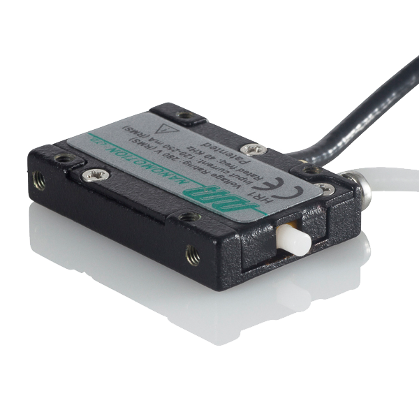
Image: Nanomotion Ltd.
The temperature-torque curve
Plotting available torque versus temperature for a typical 30 mm traveling-wave motor reveals a characteristic shape:
- -40 C: 65 to 80% of rated torque (limited by reduced piezo output and high stiction)
- -20 C: 80 to 90% of rated torque
- 0 C: 90 to 95% of rated torque
- +25 C: 100% (rated condition)
- +50 C: 90 to 100% of rated torque (friction effects begin to dominate)
- +70 C: 80 to 90% of rated torque
- +85 C: 70 to 85% of rated torque
The usable torque window across the full military temperature range (-40 to +85 C) is roughly 65 to 100% of the rated value. System designers must size the motor for the worst-case condition, meaning the motor may be 20 to 35% oversized for benign conditions.
Altitude effects
Reduced convection cooling
As altitude increases, air density decreases. At 5,000 m, air density is approximately 60% of sea level; at 10,000 m, approximately 34%; at 15,000 m, approximately 16%. Since natural and forced convection cooling rates are proportional to air density (to first approximation), the motor's ability to reject heat diminishes with altitude.
For a motor that runs at 85 C stator temperature in continuous operation at sea level with 25 C ambient, the same operating point at 10,000 m altitude would result in a stator temperature of approximately:
T_stator = T_ambient + (P_dissipated / h_convection)
If h_convection drops by 66% (proportional to the density decrease), the temperature rise above ambient increases by a factor of approximately 3. If the sea-level temperature rise is 60 C (from 25 C ambient to 85 C stator), the altitude temperature rise would be approximately 180 C, resulting in a stator temperature of 205 C. This is clearly unacceptable, exceeding the safe operating limit for PZT ceramics.
In practice, this means the motor must be derated at altitude, or active cooling must be provided, or the duty cycle must be reduced. The derating factor for continuous operation depends on altitude:
| Altitude (m) | Air density ratio | Convection reduction | Continuous torque derating |
|---|---|---|---|
| Sea level | 1.00 | None | 100% |
| 3,000 | 0.74 | 26% | 85 to 90% |
| 5,000 | 0.60 | 40% | 70 to 80% |
| 8,000 | 0.43 | 57% | 55 to 65% |
| 10,000 | 0.34 | 66% | 40 to 55% |
| 15,000 | 0.16 | 84% | 20 to 35% |
These figures assume natural convection cooling only. Many UAV gimbal installations have some airflow over the motor from the vehicle's forward motion, which significantly improves cooling. At 30 m/s airspeed, forced convection can be 5 to 10 times more effective than natural convection, substantially mitigating the altitude derating.
Reduced air pressure and outgassing
At 15,000 m, atmospheric pressure is approximately 12 kPa (versus 101 kPa at sea level). This low pressure environment introduces concerns:
- Outgassing of organic materials: Adhesives, potting compounds, and lubricants used in the motor assembly may outgas at reduced pressure. For motors qualified to MIL-STD-810 Method 500.6, altitude testing verifies that outgassing does not cause loss of function.
- Dielectric breakdown: At reduced pressure, the dielectric breakdown voltage of air decreases. Piezo motor drive signals operate at 100 to 200 Vpp at 30 to 80 kHz. The Paschen curve minimum for air occurs at approximately 1 kPa and a gap of 7.5 um, where breakdown voltage drops to approximately 330 V. At 12 kPa and typical motor electrode spacings (0.5 to 2 mm), breakdown voltage is well above 1 kV, so this is generally not a concern for standard motors. However, at extreme altitudes (above 20,000 m) or for motors with very tight electrode clearances, arcing becomes a real risk.
- Bearing behavior: If the motor uses ball bearings (common for the output shaft), the bearing lubricant may lose volatiles at low pressure, reducing lubrication effectiveness. Space-rated greases (such as Braycote 601) address this for extreme altitude applications.
Altitude-temperature combined effects
The most challenging scenario is high altitude combined with cold soak. At 10,000 m, the standard atmosphere temperature is -50 C. The motor faces simultaneously reduced piezoelectric output, high stiction, and poor convection cooling. The reduced cooling is partially offset by the reduced losses (lower Qm losses at cold), but the startup torque problem is exacerbated because the motor cannot use a warm-up period at altitude without some form of heating.
Practical solutions include:
- Integrated heaters: Small resistive heaters (1 to 3 W) bonded to the stator can bring the motor to -20 C or above within 2 to 5 minutes, ensuring reliable startup.
- Over-drive at startup: Briefly increasing the drive voltage by 20 to 30% during startup provides the additional torque needed to overcome cold stiction. This must be time-limited (typically under 1 second) to avoid depolarization of the piezoceramic.
- Pre-mission warm-up: Running the motor in a light-load condition for 30 to 60 seconds before the mission begins, using the motor's own internal losses as a heat source.
Humidity and condensation
Moisture ingress
Piezoelectric ceramics are hydrophobic and not directly affected by humidity. However, the motor assembly contains other materials that are moisture-sensitive:
- Adhesive bonds: Epoxy adhesives bonding the piezoceramic to the stator body can absorb moisture, swelling by 0.1 to 0.5% and reducing bond strength. For motors operating in tropical environments (35 C, 95% RH), accelerated aging studies show bond strength reductions of 5 to 15% after 2,000 hours of exposure.
- Electrical connections: Solder joints and wire insulation can corrode in humid environments. Conformal coating of the electrical connections is standard practice for military-grade motors.
- Friction interface: Moisture on the stator-rotor contact surface can dramatically alter friction behavior. Water acts as a lubricant, reducing friction coefficient by 30 to 60% and correspondingly reducing output torque. Motors intended for humid environments must use sealed enclosures or hydrophobic surface treatments.
Condensation
Condensation occurs when the motor temperature drops below the dew point of the surrounding air. This is common in two scenarios:
- Rapid descent from altitude: A UAV descending from 5,000 m (temperature -15 C) to sea level (temperature 30 C, 80% RH) can experience condensation on all cold surfaces, including inside the motor if it is not hermetically sealed.
- Dawn/dusk operation in humid environments: Radiative cooling during night can drop the gimbal temperature below the dew point by several degrees.
Condensation on the friction interface causes immediate torque reduction and can cause the motor to stall. Condensation on electrical connections can cause short circuits or drive signal arcing. The standard mitigation is hermetic or semi-hermetic sealing of the motor assembly, with a desiccant pack or dry nitrogen fill for long-service-life applications.
Salt fog and corrosion
For maritime UAV operations, salt fog exposure (per MIL-STD-810, Method 509.6) adds corrosion risk. The stator body (typically phosphor bronze or stainless steel) and rotor (typically aluminum with a hard anodized or ceramic-coated contact surface) must be corrosion-resistant. The piezoceramic itself is inert to salt fog, but exposed electrode metallization (silver or nickel) can corrode if not protected.
Qualification and testing approaches
Relevant military standards
Piezo motors for UAV applications are typically qualified against subsets of the following standards:
-
MIL-STD-810H: Environmental engineering considerations and laboratory tests. Key methods include:
- Method 501.7 (High temperature)
- Method 502.7 (Low temperature)
- Method 503.7 (Temperature shock)
- Method 507.6 (Humidity)
- Method 514.8 (Vibration)
- Method 516.8 (Shock)
- Method 500.6 (Low pressure / altitude)
-
MIL-STD-461G: Electromagnetic interference and compatibility. Relevant because ultrasonic motors emit electromagnetic radiation at the drive frequency and its harmonics (30 to 250 kHz), which can interfere with sensitive receivers on the UAV.
-
DO-160G (for civil aviation applications): Environmental conditions and test procedures for airborne equipment. Sections 4 (temperature and altitude), 5 (temperature variation), 6 (humidity), 7 (shock), and 8 (vibration) are directly applicable.
Test protocol for piezo motor qualification
A thorough qualification program for a piezo motor intended for UAV gimbal service includes the following sequence:
-
Baseline characterization: Measure torque-speed curves, power consumption, and efficiency at 25 C, sea level. Record resonant frequency, impedance, and vibration amplitude.
-
Temperature cycling: 100 to 500 cycles between -40 C and +85 C with 2 C/minute transition rate and 30-minute dwells at extremes. Re-characterize after cycling to check for degradation.
-
Thermal operating performance: Measure torque-speed curves at -40 C, -20 C, 0 C, +25 C, +50 C, +70 C, and +85 C. Verify startup under load at each temperature.
-
Altitude testing: Operate motor in a thermal-vacuum chamber at 12 kPa (equivalent to 15,000 m) and -50 C. Verify startup and continuous operation. Monitor for arcing or outgassing.
-
Humidity exposure: 240 hours at 50 C, 95% RH per MIL-STD-810 Method 507.6, Procedure II (aggravated cycle). Re-characterize after exposure.
-
Vibration: Sinusoidal sweep (5 to 2,000 Hz) and random vibration per MIL-STD-810 Method 514.8, Category 7 (jet aircraft stores) or Category 9 (helicopter). Verify motor operation during vibration exposure.
-
Mechanical shock: 40 g, 11 ms half-sine per MIL-STD-810 Method 516.8, Procedure I. Verify motor operation after shock.
-
EMI/EMC: Conducted and radiated emissions per MIL-STD-461G, CE102 and RE102. Conducted and radiated susceptibility per CS101, CS114, RS103.
-
Life testing: Continuous operation at rated torque and speed, at 25 C and at worst-case temperature (typically 70 C), until failure or until the required life (typically 3,000 to 5,000 hours) is demonstrated.
Accelerated life testing
Full life testing at rated conditions requires running the motor for thousands of hours, which is impractical for rapid development programs. Accelerated life testing uses elevated stress levels (higher load, higher temperature, or both) to induce failure mechanisms in shorter time. The Arrhenius model is commonly used for temperature-accelerated testing:
AF = exp[Ea/k * (1/T_use - 1/T_test)]
Where Ea is the activation energy for the dominant failure mechanism, k is Boltzmann's constant, and T is absolute temperature. For piezo motor friction interface wear, Ea is typically 0.5 to 0.8 eV, giving acceleration factors of 4 to 8x for testing at 85 C versus use at 40 C. A 500-hour test at 85 C thus demonstrates 2,000 to 4,000 hours of life at 40 C.
Derating guidelines
Based on the above analysis, the following derating table provides practical guidance for system designers. All values are expressed as a percentage of the 25 C, sea-level rated performance.
Torque derating
| Temperature (C) | Sea level | 3,000 m | 5,000 m | 10,000 m |
|---|---|---|---|---|
| -40 | 65% | 60% | 55% | 45% |
| -20 | 80% | 75% | 70% | 60% |
| 0 | 92% | 87% | 80% | 70% |
| +25 | 100% | 90% | 82% | 70% |
| +50 | 95% | 82% | 72% | 58% |
| +70 | 85% | 72% | 60% | 45% |
| +85 | 75% | 60% | 48% | 35% |
Life derating
| Temperature (C) | Relative life (% of rated) |
|---|---|
| -20 | 120 to 150% (slower wear) |
| 0 | 110 to 130% |
| +25 | 100% (rated) |
| +50 | 60 to 80% |
| +70 | 35 to 55% |
| +85 | 20 to 40% |
These are representative values for well-designed traveling-wave motors with ceramic friction interfaces. Specific motors may deviate significantly; always obtain manufacturer data for the specific motor in question.
Common failure modes outside lab conditions
Startup failure at cold
As discussed, this is the most common field failure. The motor hums (the stator vibrates) but the rotor does not turn. Caused by insufficient torque margin between the reduced piezoelectric output and the elevated stiction at low temperature. Mitigation: motor heaters, startup over-drive, larger motor with greater torque margin.
Thermal runaway
At high temperature and high load, the motor's internal losses heat the stator, which increases losses further (due to decreasing Qm), creating a positive feedback loop. If the thermal path cannot dissipate the heat (as at altitude with reduced convection), the stator temperature can climb rapidly, damaging the piezoceramic. Mitigation: thermal monitoring with automatic derating, adequate heat sinking, duty cycle limits.
Friction interface contamination
Condensation, dust, or outgassed organics on the stator-rotor contact surface alter friction behavior unpredictably. Contamination typically manifests as erratic speed control, audible noise change, or intermittent stalling. Mitigation: sealed motor enclosure, clean assembly practices, friction surface materials that are less sensitive to contamination.
Piezoceramic cracking
Thermal shock (rapid temperature transitions exceeding 5 C/minute through a large delta) can crack the bonded piezoceramic elements due to CTE mismatch with the metallic stator body. Cracked ceramics reduce vibration amplitude and can cause complete motor failure. Mitigation: design for CTE matching (use Kovar or Invar stator substrates where possible), qualify to the expected thermal shock profile.
Resonant frequency drift
The stator's resonant frequency shifts with temperature (typically -0.05 to -0.15%/C for PZT stators). Over the -40 to +85 C range, this amounts to a 2 to 4% frequency shift, or 600 Hz to 3.2 kHz for a 40 kHz motor. The drive electronics must track this shift to maintain optimal performance. Modern controllers use automatic frequency tracking (typically by monitoring the impedance phase or the motional current), but the tracking range and response speed must be validated across the full temperature range.
Design recommendations
Based on field experience and the analysis above, the following practices improve piezo motor reliability outside lab conditions:
-
Oversize by 30 to 50%: Select a motor with rated torque 1.3 to 1.5 times the required operating torque at 25 C. This provides margin for temperature and altitude derating without pushing the motor into its nonlinear operating region.
-
Implement thermal management: Even a simple conductive path (copper strap or aluminum bracket) from the motor body to a heat sink significantly improves high-temperature and altitude performance. For extreme environments, an integrated heater for cold start and a thermistor for thermal monitoring are worthwhile additions.
-
Seal the motor: An IP54 or better seal prevents moisture and dust contamination of the friction interface. The small additional mass (typically 5 to 10 g for O-ring seals and a labyrinth on the output shaft) is well justified.
-
Validate across the envelope: Do not extrapolate from room-temperature data. Test the motor at the corners of the operational envelope: cold/low altitude, cold/high altitude, hot/low altitude, hot/high altitude. Startup testing at the cold extreme is particularly important.
-
Use automatic frequency tracking: Fixed-frequency drives will lose performance as temperature changes shift the stator resonance. Adaptive drive electronics add modest cost but ensure consistent performance across the temperature range.
-
Plan for life reduction: If the operational profile includes significant time at elevated temperature, apply the life derating factors and plan maintenance or replacement intervals accordingly.
Conclusion
Piezoelectric ultrasonic motors can operate reliably across the full military temperature range (-40 to +85 C) and at altitudes up to 15,000 m, but only with appropriate design measures and realistic expectations. The key derating factors are 20 to 35% torque reduction at temperature extremes and 30 to 65% torque reduction at high altitude (depending on cooling provisions). Cold startup and thermal management are the dominant design challenges. A systematic qualification program, following MIL-STD-810 or DO-160 test methods, validates performance and identifies weaknesses before they become field failures. Designers who account for these environmental factors from the outset, rather than treating them as afterthoughts, will build systems that deliver consistent performance from the test bench to the operational theater.