Fundamentals
The piezoelectric effect: from crystal structure to force generation
How atomic asymmetry in ceramics creates the mechanical forces that drive ultrasonic motors
Why piezoelectricity matters for motion
Every ultrasonic piezoelectric motor begins with a simple physical phenomenon: certain crystals develop an electric charge when mechanically stressed, and conversely, deform when an electric field is applied. This is the piezoelectric effect. Understanding it at the crystal level is not academic trivia. It directly determines how much force a motor can generate, how fast a stator can oscillate, and how efficiently electrical energy converts to mechanical motion. Engineers who skip this foundation end up mystified when a motor that "should" work on paper fails on the bench. The way these ceramic properties translate into motion is explored in how ultrasonic piezoelectric motors work.
This article traces the piezoelectric effect from its origins in crystal symmetry through the practical engineering coefficients that appear on ceramic datasheets, and finally connects those numbers to motor-level performance. Along the way, it provides worked examples, quantitative comparisons across PZT families, and data tables that you can reference during design.
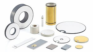
Image: Physik Instrumente (PI)
Crystal symmetry and the origin of piezoelectricity
Piezoelectricity arises from the absence of a center of symmetry in a crystal's unit cell. Of the 32 crystallographic point groups, 21 lack inversion symmetry. Of those, 20 exhibit piezoelectricity. (The lone exception, cubic class 432, lacks inversion symmetry but has other symmetry elements that cancel the effect.) When mechanical stress displaces ions in an asymmetric unit cell, the positive and negative charge centers no longer coincide. A net electric dipole appears. Sum that dipole over billions of unit cells and you get a measurable voltage across the crystal faces.
The perovskite structure in detail
The materials most relevant to ultrasonic motors share the perovskite crystal structure, with the general formula ABO3. In PZT, the A-site is occupied by lead (Pb2+), and the B-site by either zirconium (Zr4+) or titanium (Ti4+). Oxygen atoms (O2-) form an octahedral cage around the B-site ion.
Above the Curie temperature, the perovskite unit cell is cubic: the B-site ion sits precisely at the center of the oxygen octahedron, and the structure has a center of symmetry. No piezoelectricity is possible. Below the Curie temperature, the unit cell distorts. In the tetragonal phase, the B-site ion shifts slightly along one axis (the c-axis), and the oxygen octahedron elongates in the same direction. This displacement, typically 10 to 20 picometres, breaks the inversion symmetry and creates a spontaneous electric dipole within each unit cell.
The magnitude of this spontaneous polarization is substantial. For PZT near the morphotropic phase boundary, the spontaneous polarization Ps is approximately 0.30 to 0.40 C/m2. For comparison, barium titanate (BaTiO3) has Ps of approximately 0.26 C/m2, and lithium niobate (LiNbO3) approximately 0.71 C/m2.
Ferroelectric domains
In a single crystal below the Curie temperature, the spontaneous polarization could point along any of several crystallographically equivalent directions. In tetragonal PZT, there are six equivalent [100]-type directions. The crystal breaks into domains, each uniformly polarized along one of these directions. Domain walls, typically 1 to 10 nm thick, separate adjacent domains. The domain pattern minimizes the total energy (electrical, elastic, and domain-wall energy).
In a polycrystalline ceramic, each grain is a single crystal with its own lattice orientation. Within each grain, domains form according to the grain's crystallographic axes. The result is a complex, three-dimensional mosaic of domains with polarization vectors pointing in essentially random directions. The net macroscopic polarization is zero, and the bulk ceramic is electromechanically inert until it is poled.
Natural quartz (SiO2) was the first material exploited for the piezoelectric property, famously by the Curie brothers in 1880. Quartz is stable and has excellent frequency characteristics, which is why it still dominates clock oscillators. But its piezoelectric coefficients are small. For motor applications, where large displacements and high forces matter, engineered ceramics outperform quartz by orders of magnitude.
The direct and converse effects
The piezoelectric effect has two complementary manifestations:
Direct effect. Apply mechanical stress to a piezoelectric material and it generates an electric charge (or voltage across its electrodes). This is the basis of piezoelectric sensors, accelerometers, and energy harvesters. The relationship is:
D = d * T + epsilon * E
where D is electric displacement, d is the piezoelectric strain coefficient, T is mechanical stress, epsilon is permittivity, and E is electric field. In a sensor application with no applied field (E = 0), the charge generated is directly proportional to the applied stress through the d coefficient.
Converse effect. Apply an electric field to a piezoelectric material and it mechanically deforms. This is what drives piezoelectric motors. The strain produced is:
S = s * T + d * E
where S is strain, s is elastic compliance, and the other variables are as above. With no external mechanical load (T = 0), the strain is directly proportional to the applied field through the same d coefficient.
The symmetry here is important: the same d coefficient governs both effects. A material that is a good sensor is, by the same physics, a good actuator. This is not a coincidence; it is a thermodynamic requirement of a linear reversible coupling between electrical and mechanical energy.
Electrostriction versus piezoelectricity
All dielectric materials exhibit electrostriction, a strain proportional to the square of the applied electric field. Electrostriction is symmetric: the material deforms the same way regardless of field polarity. Piezoelectricity, by contrast, produces a strain that reverses sign when the field reverses. At the drive levels used in ultrasonic motors (10 to 200 V across 0.5 to 2 mm of PZT), the piezoelectric strain dominates the electrostrictive contribution by a factor of 100 or more. However, electrostriction becomes relevant in relaxor ferroelectrics (PMN, PMN-PT) used in some specialized actuator applications, where the distinction between the two effects blurs.
Lead zirconate titanate: the dominant motor ceramic
While many materials are piezoelectric (quartz, lithium niobate, tourmaline, zinc oxide, PVDF polymer, various lead-free ceramics), the workhorse material for ultrasonic motors is lead zirconate titanate, Pb(ZrxTi1-x)O3, universally abbreviated PZT.
PZT is a solid solution of lead zirconate (PbZrO3, antiferroelectric) and lead titanate (PbTiO3, ferroelectric). The magic happens near the morphotropic phase boundary (MPB), at approximately x = 0.52 (52% Zr, 48% Ti). At this composition, the crystal structure sits at the boundary between rhombohedral and tetragonal phases. The free energy landscape is nearly flat between the two phases, which means the lattice can polarize in many directions with minimal energy cost. The result: piezoelectric coefficients peak sharply at the MPB.
Commercial PZT families: comprehensive comparison
Commercially, PZT compositions are grouped into "soft" and "hard" families, distinguished by dopant additions that modify domain wall mobility. The following table provides a comprehensive comparison of common PZT types alongside other piezoelectric materials relevant to motor design.
| Property | PZT-4 (Navy I) | PZT-8 (Navy III) | PZT-5A (Navy II) | PZT-5H (Navy VI) | PZT-5J | BaTiO3 | LiNbO3 |
|---|---|---|---|---|---|---|---|
| d33 (pC/N) | 289 | 225 | 374 | 593 | 500 | 190 | 6 |
| d31 (pC/N) | -123 | -97 | -171 | -274 | -210 | -78 | -1 |
| d15 (pC/N) | 496 | 330 | 584 | 741 | 620 | 260 | 68 |
| k33 | 0.70 | 0.64 | 0.71 | 0.75 | 0.73 | 0.49 | 0.23 |
| k31 | 0.33 | 0.30 | 0.34 | 0.39 | 0.36 | 0.21 | 0.02 |
| kp | 0.58 | 0.51 | 0.60 | 0.65 | 0.62 | 0.33 | N/A |
| Qm | 500 | 1000 | 75 | 65 | 70 | 300 | 10000 |
| tan delta (%) | 0.4 | 0.3 | 2.0 | 2.0 | 1.8 | 1.0 | 0.1 |
| Tc (C) | 328 | 300 | 365 | 193 | 250 | 120 | 1150 |
| epsilon33/epsilon0 | 1300 | 1000 | 1700 | 3400 | 2700 | 1700 | 29 |
| Density (kg/m3) | 7500 | 7600 | 7750 | 7500 | 7600 | 5700 | 4640 |
| sE11 (pm2/N) | 12.3 | 11.5 | 16.4 | 16.5 | 15.0 | 8.6 | 5.8 |
| sE33 (pm2/N) | 15.5 | 13.5 | 18.8 | 20.7 | 18.0 | 8.6 | 5.0 |
| Coercive field Ec (kV/mm) | 1.4 | 1.7 | 0.5 | 0.4 | 0.6 | 0.2 | 21 |
The practical interpretation for motor designers:
- PZT-4 (Navy Type I): The standard choice for ultrasonic motors. High Qm (500) means low losses under continuous resonant drive. The d33 of 289 pC/N is adequate for most motor designs. The coercive field of 1.4 kV/mm provides good resistance to depolarization under AC drive.
- PZT-8 (Navy Type III): Even harder than PZT-4, with Qm exceeding 1000. Designed specifically for high-power resonant applications where thermal management is critical. The trade-off is lower d coefficients (d33 = 225 pC/N), meaning less displacement per volt. Used in high-power sonar transducers and industrial ultrasonic welding horns as well as motors.
- PZT-5A (Navy Type II): Higher d coefficients (d33 = 374 pC/N) than PZT-4, making it attractive for sensors and low-duty-cycle actuators. The low Qm (75) makes it unsuitable for continuous resonant drive; it would overheat within minutes.
- PZT-5H (Navy Type VI): The highest d coefficients (d33 = 593 pC/N) of the standard commercial grades. Preferred where maximum sensitivity or maximum quasi-static displacement matters. The Curie temperature of only 193 C and the low Qm of 65 make it wholly unsuitable for ultrasonic motor service.
- PZT-5J: An intermediate soft composition sometimes used in hybrid actuator/sensor designs. Not suitable for continuous motor drive.
Soft versus hard: why dopants matter
The distinction between "soft" and "hard" PZT arises from the type of dopant substituted into the perovskite lattice:
Donor dopants (e.g., La3+ replacing Pb2+, or Nb5+ replacing Zr4+/Ti4+) create lead vacancies. These vacancies increase domain wall mobility, resulting in higher d coefficients, lower Qm, higher dielectric losses, and lower coercive field. These are the "soft" compositions.
Acceptor dopants (e.g., Fe3+ or Mn2+ replacing Zr4+/Ti4+) create oxygen vacancies. These vacancies pin domain walls, making them harder to move. The result is lower d coefficients, higher Qm, lower dielectric losses, and higher coercive field. These are the "hard" compositions that motors require.
The oxygen vacancy pinning mechanism is critical for motor applications. Under sustained AC drive, domain walls oscillate back and forth. In soft PZT, these oscillations are large and dissipative, converting electrical energy to heat. In hard PZT, the pinned domain walls vibrate only slightly, keeping losses low. This is why Qm differs by a factor of 10 to 15 between soft and hard grades.
The lead-free question
RoHS and REACH regulations have driven significant research into lead-free piezoceramics. The main contender families are compared below.
| Property | PZT-4 (reference) | BaTiO3 | KNN (optimized) | BNT-BT | BCTZ |
|---|---|---|---|---|---|
| d33 (pC/N) | 289 | 190 | 300-450 | 150-200 | 500-620 |
| Qm | 500 | 300 | 200-400 | 100-200 | 50-100 |
| Tc or Td (C) | 328 | 120 | 400-420 | 150-200 | 60-90 |
| tan delta (%) | 0.4 | 1.0 | 1.0-3.0 | 1.5-3.0 | 2.0-4.0 |
| d33 * Qm (10^3) | 145 | 57 | 60-180 | 15-40 | 25-62 |
| Maturity | Production | Production | Lab/pilot | Lab/pilot | Lab |
| Cost (relative) | 1x | 0.7x | 2-3x | 2-3x | 3-5x |
Key observations for the motor engineer:
- BaTiO3 has been a production material for decades, but its low Curie temperature (120 C) and moderate d33 limit its usefulness. It works in room-temperature, low-power applications.
- KNN (sodium potassium niobate) is the most promising lead-free candidate. Laboratory samples have reached d33 values above 400 pC/N, and the Curie temperature exceeds 400 C, significantly higher than PZT. However, achieving high Qm simultaneously with high d33 has proven difficult. The product d33 * Qm, which determines performance in resonant motors, remains lower than PZT-4 in most published results.
- BNT-BT (bismuth sodium titanate, barium titanate) offers moderate d33 but suffers from a depolarization temperature (Td) well below the Curie temperature, limiting the usable range to roughly 100 to 150 C.
- BCTZ (barium calcium titanate zirconate) has generated excitement for its very high d33 values (reportedly exceeding 600 pC/N in textured ceramics), but its depolarization temperature is below 100 C, and its Qm is too low for resonant motor applications.
Piezoelectric motors currently hold a RoHS exemption (Exemption 7(c)-I) for lead content in PZT. This exemption is reviewed every few years; the most recent renewal extends through 2027. The practical outlook: no lead-free material is ready to replace PZT in high-performance ultrasonic motors as of 2026. Motor designers should track KNN development closely, especially compositions doped with CuO or MnO that aim to raise Qm, but should not specify lead-free ceramics for production motor applications without extensive qualification testing.
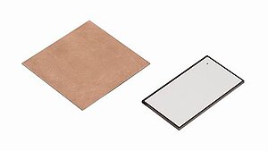
Image: Physik Instrumente (PI)
Piezoelectric coefficients: d33, d31, and what they mean
The piezoelectric strain coefficient d relates the strain produced per unit electric field (converse effect) or the charge produced per unit stress (direct effect). Because piezoelectric materials are anisotropic (their properties depend on direction), d is actually a third-rank tensor. In practice, engineers work with specific components of that tensor, using a compressed matrix notation with two subscripts.
The first subscript indicates the direction of the electric field (or charge), numbered 1, 2, 3 corresponding to x, y, z. The 3-direction is always defined as the poling direction. The second subscript indicates the direction of mechanical strain (or stress), using the same numbering for normal strains (1-3) and additional numbers 4-6 for shear strains.
d33 is the longitudinal coefficient: strain in the poling direction caused by a field in the poling direction. For PZT-4, d33 is approximately 289 pC/N (or equivalently, 289 pm/V). This means that applying 1 V/m of electric field produces 289 x 10^-12 meters of strain per meter of material length, measured along the poling axis.
d31 is the transverse coefficient: strain perpendicular to the poling direction caused by a field in the poling direction. For PZT-4, d31 is approximately -123 pC/N. The negative sign is physically meaningful: when the material elongates in the 3-direction under a positive field, it contracts in the 1- and 2-directions (Poisson-like coupling). Many ultrasonic motor designs exploit d31 to generate bending or tangential motion in thin plates or rings.
d15 is the shear coefficient: shear strain in a plane containing the poling direction, caused by a field perpendicular to the poling direction. For PZT-4, d15 is approximately 496 pC/N, often the largest coefficient. Some motor designs exploit shear modes for motion generation.
Worked example 1: free displacement of a PZT-4 disc
A single PZT-4 disc, 1 mm thick, driven at 100 V, produces a free (unloaded) strain of:
S = d33 * E = 289 x 10^-12 * (100 / 0.001) = 289 x 10^-12 * 10^5 = 28.9 x 10^-6
That is about 29 microstrain, corresponding to 29 nanometers of displacement for the 1 mm disc.
Worked example 2: multilayer stack actuator
Now consider a multilayer stack actuator with 100 layers, each 100 micrometres thick, driven at 150 V. The total active length is 100 x 0.1 mm = 10 mm. The field in each layer is:
E = 150 V / 0.0001 m = 1.5 x 10^6 V/m = 1.5 kV/mm
The strain per layer is:
S = d33 * E = 289 x 10^-12 * 1.5 x 10^6 = 434 x 10^-6
The displacement per layer is:
delta_layer = S * t_layer = 434 x 10^-6 * 0.0001 m = 43.4 nm
The total stack displacement is:
delta_total = 100 * 43.4 nm = 4.34 micrometres
At 150 V across 100 micrometre layers, the field is 1.5 kV/mm, which is close to the coercive field for PZT-4 (1.4 kV/mm). In practice, you would not operate this close to the coercive field to avoid depolarization. A more conservative design might use 100 V drive:
E = 100 / 0.0001 = 1.0 x 10^6 V/m = 1.0 kV/mm delta_total = 100 * (289 x 10^-12 * 10^6 * 10^-4) = 100 * 28.9 nm = 2.89 micrometres
Worked example 3: transverse (d31) bending actuator
A bimorph bending actuator consists of two PZT-5A layers (each 0.25 mm thick) bonded together with opposite poling. The active length is 20 mm. Driven at 100 V:
E = 100 / 0.00025 = 400,000 V/m = 0.4 kV/mm
The free strain in each layer is:
S = d31 * E = -171 x 10^-12 * 4 x 10^5 = -68.4 x 10^-6
For a bimorph, the tip deflection (free end) is approximately:
delta_tip = (3/4) * d31 * V * (L/t)^2 / t
where L is the length, t is the total thickness, and V is the applied voltage.
delta_tip = 0.75 * 171 x 10^-12 * 100 * (0.02 / 0.0005)^2 / 0.0005
delta_tip = 0.75 * 171 x 10^-12 * 100 * 1600 / 0.0005
delta_tip = 0.75 * 171 x 10^-12 * 320,000
delta_tip = 0.75 * 54.7 x 10^-6 = 41 micrometres
This illustrates why bending actuators produce much larger displacements than longitudinal stacks, at the cost of much lower stiffness and force.
Worked example 4: displacement at resonance
Returning to the PZT-4 disc from Example 1, now operated at its resonant frequency with Qm = 500:
Off-resonance displacement: 29 nm On-resonance displacement: 29 nm * 500 = 14,500 nm = 14.5 micrometres
This is the displacement amplification that makes ultrasonic motors possible. A PZT-8 disc of the same dimensions (d33 = 225 pC/N, Qm = 1000) would produce:
Off-resonance: 225 x 10^-12 * 10^5 * 10^-3 = 22.5 nm On-resonance: 22.5 nm * 1000 = 22,500 nm = 22.5 micrometres
Despite having a 22% lower d33, PZT-8 produces 55% more displacement at resonance because of its higher Qm. This is why the product d * Qm is the relevant figure of merit for resonant motor applications, not d alone.
| Ceramic | d33 (pC/N) | Qm | d33 * Qm | Off-resonance delta (nm, 100V/mm) | On-resonance delta (um, 1mm disc) |
|---|---|---|---|---|---|
| PZT-4 | 289 | 500 | 144,500 | 29.0 | 14.5 |
| PZT-8 | 225 | 1000 | 225,000 | 22.5 | 22.5 |
| PZT-5A | 374 | 75 | 28,050 | 37.4 | 2.8 |
| PZT-5H | 593 | 65 | 38,545 | 59.3 | 3.9 |
This table explains, in a single row of numbers, why soft PZT fails in motors despite having higher d coefficients.
Poling: turning a ceramic into a transducer
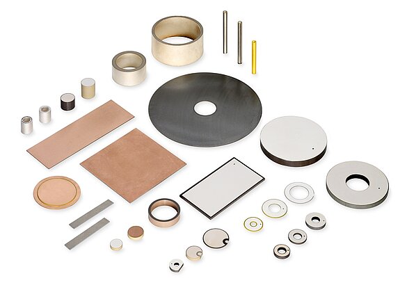
Image: PZT piezoceramic components in the geometries most common for motor and actuator fabrication. Source: PI (Physik Instrumente)
Raw PZT ceramic, as it comes out of the sintering furnace, is not piezoelectric. The material is ferroelectric, meaning each microscopic grain contains domains with spontaneous polarization. But those domains are randomly oriented. The net polarization, averaged over the bulk, is zero. The material is electromechanically inert.
Poling is the process that aligns domains to create a net macroscopic polarization. The procedure is straightforward in principle:
- Electrode the ceramic (typically by sputtering or screen-printing silver or nickel electrodes on opposite faces).
- Heat the ceramic to a temperature well below the Curie point but high enough to increase domain wall mobility (typically 100 to 150 C for PZT-4).
- Apply a strong DC electric field, typically 2 to 4 kV/mm, across the electrodes.
- Hold the field while slowly cooling the ceramic back to room temperature.
- Remove the field. The domains remain partially aligned.
"Partially" is the key word. In a polycrystalline ceramic, grains are randomly oriented. Even under a strong poling field, domains can only rotate to the crystallographic axis closest to the field direction, not to an arbitrary direction. For tetragonal PZT, this means domains can align along the six equivalent [100] directions; only those within roughly 45 degrees of the field direction will switch. The result is that the effective d33 of a poled ceramic is typically 30% to 50% of the single-crystal value.
Poling conditions for common PZT types
| PZT Type | Poling temperature (C) | Poling field (kV/mm) | Poling time (min) | Achievable P_r/P_s |
|---|---|---|---|---|
| PZT-4 | 120-150 | 2.0-3.0 | 15-30 | 0.83-0.90 |
| PZT-8 | 130-160 | 2.5-3.5 | 20-40 | 0.80-0.87 |
| PZT-5A | 80-120 | 1.5-2.5 | 10-20 | 0.90-0.95 |
| PZT-5H | 60-100 | 1.0-2.0 | 5-15 | 0.92-0.97 |
The ratio P_r/P_s (remanent polarization divided by spontaneous polarization) indicates how well the poling process has aligned the domains. Soft compositions achieve higher alignment because their domain walls are more mobile.
Depoling risks
The carefully established domain alignment can be destroyed by:
- Exceeding the Curie temperature. Above Tc, the material transitions from ferroelectric to paraelectric (cubic symmetry, centrosymmetric). All domain structure is lost. For PZT-4, Tc is approximately 328 C. In ultrasonic motor applications, stator temperatures rarely exceed 80 C under normal operation, providing comfortable margin.
- Excessive mechanical stress. Very high compressive stress along the poling direction (typically above 50 to 100 MPa for PZT-4) can cause domain switching that partially or fully depoles the ceramic. Tensile stress perpendicular to the poling direction has a similar effect at lower thresholds (20 to 50 MPa).
- Excessive electric field opposite to the poling direction. The coercive field for PZT-4 is approximately 1.0 to 1.5 kV/mm. Applying a field exceeding this value in the reverse direction will repolarize (or depole) the ceramic.
- Sustained high-amplitude AC drive. Even below the coercive field, repeated cycling at high amplitude causes gradual domain reorganization and property drift. This is why hard PZT compositions (PZT-4, PZT-8) with higher coercive fields and more stable domain walls are preferred for resonant motor applications.
Temperature dependence of piezoelectric properties
Piezoelectric coefficients are not constant; they vary with temperature. For motor designers, this variation has direct consequences for drive level, resonant frequency, and long-term stability, making thermal behaviour one of the primary engineering challenges in deployed systems.
| Property | PZT-4 at 25 C | PZT-4 at 100 C | PZT-4 at 200 C | PZT-8 at 25 C | PZT-8 at 100 C | PZT-8 at 200 C |
|---|---|---|---|---|---|---|
| d33 (pC/N) | 289 | 310 (+7%) | 340 (+18%) | 225 | 240 (+7%) | 265 (+18%) |
| d31 (pC/N) | -123 | -132 (+7%) | -146 (+19%) | -97 | -104 (+7%) | -116 (+20%) |
| epsilon33/e0 | 1300 | 1450 (+12%) | 1700 (+31%) | 1000 | 1100 (+10%) | 1300 (+30%) |
| Qm | 500 | 400 (-20%) | 250 (-50%) | 1000 | 800 (-20%) | 500 (-50%) |
| kp | 0.58 | 0.59 (+2%) | 0.60 (+3%) | 0.51 | 0.52 (+2%) | 0.53 (+4%) |
| tan delta (%) | 0.4 | 0.5 (+25%) | 0.8 (+100%) | 0.3 | 0.4 (+33%) | 0.6 (+100%) |
The trends are consistent across all PZT compositions: d coefficients increase with temperature (the material becomes more responsive), but Qm decreases (the material becomes lossier). The increase in d is a benefit for quasi-static actuators but a mixed blessing for resonant motors, because the Qm decrease offsets much of the gain. The product d33 * Qm for PZT-4 goes from 144,500 at 25 C to 124,000 at 100 C and 85,000 at 200 C, a 41% reduction. For PZT-8, d33 * Qm drops from 225,000 to 192,000 to 132,500 over the same range.
Aging of PZT ceramics
After poling, PZT properties do not remain constant. They drift logarithmically with time, a process called aging. Aging is caused by gradual domain wall relaxation: domains slowly re-randomize, reducing the net polarization and shifting all piezoelectric, dielectric, and elastic properties. This long-term drift has direct implications for life expectancy and wear in fielded systems.
The aging rate is expressed as the fractional change per decade of time. Typical aging rates for motor-relevant properties:
| Property | PZT-4 aging rate (%/decade) | PZT-8 aging rate (%/decade) | PZT-5A aging rate (%/decade) | PZT-5H aging rate (%/decade) |
|---|---|---|---|---|
| d33 | -3 to -5 | -1 to -3 | -4 to -6 | -5 to -8 |
| epsilon33 | -3 to -5 | -2 to -3 | -4 to -7 | -6 to -10 |
| kp | -1 to -2 | -0.5 to -1 | -2 to -3 | -3 to -5 |
| Resonant freq. | +0.5 to +1.0 | +0.3 to +0.5 | +0.5 to +1.5 | +1.0 to +2.0 |
"Per decade" means per tenfold increase in time. If d33 ages by -4%/decade, it drops 4% between 1 day and 10 days after poling, another 4% between 10 days and 100 days, another 4% between 100 days and 1000 days (about 3 years), and so on. The logarithmic nature means aging is rapid immediately after poling and then slows dramatically. A ceramic that has been aged for 1 year is relatively stable for the next 10 years.
Practical implication for motor manufacturers: PZT elements should be aged for at least 30 days (and preferably 90 days) after poling before being assembled into motors and characterized. Properties measured on freshly poled ceramics will overestimate the performance of a motor measured months later. Some manufacturers "pre-age" ceramics by brief thermal treatment (heating to 100 to 150 C for a few hours), which accelerates the aging process and stabilizes properties sooner.
Resonant frequency aging is particularly relevant. A motor tuned at the factory on freshly poled ceramics will drift slightly upward in frequency over the first year. If the drive electronics have sufficient tracking range (typically plus or minus 2%), this is not a problem. If the tracking range is narrow, aging must be accounted for in the initial frequency setting.
The mechanical quality factor: why it matters for motors
Beyond d coefficients, the mechanical quality factor Qm is arguably the most important parameter for ultrasonic motor ceramics. Qm is the reciprocal of internal mechanical losses. A high Qm means the ceramic vibrates with low damping, which has two critical consequences:
-
Displacement amplification at resonance. A stator driven at resonance achieves displacement amplification proportional to Qm. If a PZT element produces 30 nm of free displacement off-resonance, operating at resonance with Qm = 1000 amplifies that to approximately 30 micrometres. This is how ultrasonic motors generate useful motion from nanometre-scale intrinsic strains.
-
Low self-heating. Internal mechanical losses convert electrical energy to heat. In a resonant device driven continuously, even modest losses compound rapidly. A soft PZT with Qm = 65 (typical for PZT-5H) will overheat quickly under the drive levels required for motor operation. A hard PZT with Qm = 500 to 2000 (PZT-4 and PZT-8) dissipates far less heat and can sustain continuous operation.
Quantifying heat dissipation
The power dissipated in the PZT due to mechanical losses is:
P_mech = (omega * U_stored) / Qm
where omega is the angular frequency (2 * pi * f) and U_stored is the peak mechanical energy stored in the vibrating element. For a PZT-4 ring element in a 40 kHz stator, with U_stored approximately 50 mJ:
P_mech = (2 * pi * 40000 * 0.050) / 500 = 25.1 W ... this is for the complete stator, not one element
For a single PZT element storing roughly 5 mJ:
P_mech = (2 * pi * 40000 * 0.005) / 500 = 2.51 W (PZT-4, Qm = 500) P_mech = (2 * pi * 40000 * 0.005) / 1000 = 1.26 W (PZT-8, Qm = 1000) P_mech = (2 * pi * 40000 * 0.005) / 65 = 19.3 W (PZT-5H, Qm = 65)
The PZT-5H element would need to dissipate nearly 20 W, which would raise its temperature by roughly 200 C within seconds in the absence of active cooling. This is why soft PZT cannot be used in resonant motor applications.
Coupling coefficient: efficiency of energy conversion
The electromechanical coupling coefficient k describes what fraction of input electrical energy is converted to mechanical energy (or vice versa). Like d, it is direction-dependent:
- k33 (longitudinal): typically 0.70 for PZT-4. This means about 49% (k^2) of input electrical energy converts to mechanical energy in the longitudinal mode.
- k31 (transverse): typically 0.33 for PZT-4. Lower efficiency, but the transverse mode is geometrically convenient for thin-plate designs.
- kp (planar): the radial coupling coefficient for thin discs, typically 0.58 for PZT-4.
- kt (thickness): the coupling coefficient for thickness-mode vibration of thin plates, typically 0.51 for PZT-4.
These numbers set an upper bound on motor efficiency. No ultrasonic motor can exceed the electromechanical coupling efficiency of its ceramic, and real motors achieve substantially less due to additional losses in the stator structure, friction interface, and drive electronics.
Theoretical maximum motor efficiency
The theoretical maximum efficiency of a piezoelectric resonator is:
eta_max = k^2 * Qm / (1 + k^2 * Qm)
For PZT-4 in the k33 mode:
eta_max = 0.49 * 500 / (1 + 0.49 * 500) = 245 / 246 = 99.6%
For PZT-4 in the k31 mode:
eta_max = 0.109 * 500 / (1 + 0.109 * 500) = 54.5 / 55.5 = 98.2%
For PZT-5H in the k33 mode:
eta_max = 0.5625 * 65 / (1 + 0.5625 * 65) = 36.6 / 37.6 = 97.3%
These high theoretical values show that the ceramic itself is not the efficiency bottleneck. Real motors achieve 30% to 50% overall efficiency because of losses in the friction interface (the dominant loss), stator structural damping, and drive electronics.
Single crystals: PMN-PT and PIN-PMN-PT
Single-crystal piezoelectrics based on relaxor ferroelectric compositions offer dramatically higher performance than polycrystalline PZT ceramics:
| Property | PZT-4 ceramic | PMN-33%PT crystal | PIN-PMN-PT crystal |
|---|---|---|---|
| d33 (pC/N) | 289 | 2000-2800 | 1200-1500 |
| d31 (pC/N) | -123 | -900 to -1300 | -600 to -800 |
| k33 | 0.70 | 0.92-0.95 | 0.88-0.92 |
| k31 | 0.33 | 0.45-0.50 | 0.40-0.45 |
| Qm | 500 | 100-200 | 300-800 |
| Tc (C) | 328 | 155 | 190-200 |
| Trt (C) | N/A | 60-90 | 100-130 |
| Cost (relative) | 1x | 50-100x | 50-100x |
The d33 values for PMN-PT are 7 to 10 times those of PZT-4, enabling proportionally larger displacements. However, several factors limit their use in motors:
- Low Curie temperature (155 C for PMN-PT) and even lower rhombohedral-to-tetragonal transition temperature Trt (60 to 90 C for PMN-PT). Operating above Trt causes an irreversible phase transition that destroys the oriented domain structure.
- Low Qm. PMN-PT crystals have Qm of only 100 to 200, negating much of their d-coefficient advantage for resonant applications. PIN-PMN-PT is better (Qm up to 800 in Mn-doped versions), making it a potential motor material.
- Cost and fragility. Single crystals are grown by the Bridgman method and are expensive (50 to 100 times PZT per unit volume). They are also more fragile than sintered ceramics.
- Size limitations. Crystal boules are typically 50 to 75 mm in diameter, limiting the size of elements that can be cut.
Single crystals see extensive use in medical ultrasound transducers and sonar arrays, where their high coupling coefficients justify the cost. For motor applications, Mn-doped PIN-PMN-PT is the most promising candidate, with a d33 * Qm product that can exceed PZT-8 in laboratory demonstrations. Commercial adoption remains limited as of 2026.
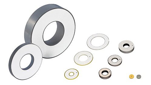
Image: Piezoceramic rings are the most common element form in traveling-wave ultrasonic motors. Ring geometry distributes the drive force uniformly around the stator circumference. Source: PI (Physik Instrumente)
From ceramic properties to motor performance
Understanding the connection between ceramic coefficients and motor behavior is essential for design:
Force generation depends primarily on d31 or d33 (depending on the motor type), the applied electric field, the elastic stiffness of the ceramic and stator assembly, and the mechanical advantage of the stator geometry. A higher d coefficient means more strain per volt, which translates to more force at the stator tip. But the relationship is not linear in the complete system because the stator structure has its own compliance and resonant characteristics.
Speed in a traveling-wave ultrasonic motor is proportional to the vibration amplitude at the stator surface and the drive frequency. The vibration amplitude depends on d * E * Qm (piezoelectric strain, amplified by resonance). Increasing any of these three factors increases speed, subject to mechanical and thermal limits.
Resolution of a stick-slip or inchworm motor relates to the minimum controllable step size, which is fundamentally limited by the intrinsic strain d * E. With d33 = 289 pC/N and sub-volt drive capability, step sizes below 1 nanometer are physically achievable, though noise, friction, and electronics often set the practical limit higher.
Efficiency is bounded by k^2 * Qm / (1 + k^2 * Qm) for the ceramic alone, with additional losses in every subsequent stage.
Lifetime depends heavily on the stability of the ceramic under sustained drive. Hard PZT compositions with high Qm and high coercive fields resist property degradation. Soft compositions drift and overheat. Applications in semiconductor manufacturing, where ceramics must perform in vacuum environments at elevated duty cycles, impose some of the most stringent demands; wafer stage positioning illustrates the engineering trade-offs in practice.
Design selection guide
The following table summarizes which PZT type to choose for different motor architectures:
| Motor type | Recommended PZT | Reason |
|---|---|---|
| Traveling-wave rotary (continuous) | PZT-4 or PZT-8 | High Qm for continuous resonant drive |
| Standing-wave linear (intermittent) | PZT-4 | Good balance of d and Qm |
| Stick-slip (quasi-static steps) | PZT-5A or PZT-4 | High d for maximum step size; low duty cycle allows soft PZT |
| Inchworm (quasi-static) | PZT-5A | Maximum d33 for clamping and stepping |
| Langevin bolt-clamped | PZT-8 | Highest Qm for maximum power handling |
| Bimorph bending | PZT-5A | High d31 for maximum deflection |
| Cryogenic motor | PZT-4 | Good d retention at low temperature; high Tc for margin |
| High-temperature motor (>150 C) | Modified PZT-4 or BiT | High Tc compositions required |
Practical takeaways
-
Match the ceramic to the application. PZT-4 is the default for standard ultrasonic motors. PZT-8 for high-power or continuous-duty applications. Soft compositions belong in sensors, not motors.
-
Respect depoling limits. Keep operating temperature well below Tc. Keep AC drive amplitude below the coercive field. Monitor stator temperature during initial testing.
-
Qm matters as much as d. A ceramic with a higher d coefficient but lower Qm can produce less displacement at resonance than a "weaker" ceramic with higher Qm. Always evaluate the product d * Qm for resonant applications.
-
d31 is not inferior to d33. Many successful motor designs exploit the transverse effect because it enables thin, flat stator geometries that are easier to manufacture and integrate. The lower coupling efficiency is offset by geometric advantages.
-
Lead-free ceramics are not yet ready for high-performance motors. Monitor the field, especially KNN-based systems, but do not specify them for production ultrasonic motor applications in 2026 without extensive qualification testing.
-
Single crystals (PMN-PT, PIN-PMN-PT) offer dramatically higher d coefficients (d33 > 2000 pC/N) and coupling (k33 > 0.90), but at much higher cost and with lower Curie temperatures. They are used in specialized applications (medical ultrasound, sonar) but have not displaced PZT ceramics in motor applications due to cost, fragility, and thermal limitations.
-
Account for aging. Specify ceramics aged for at least 30 days after poling. Include the aging-related frequency drift in your drive electronics tracking range. Expect d33 to decrease by 3 to 5% per time decade for PZT-4.
-
Temperature shifts everything. The d coefficients increase by roughly 7% per 75 C, which sounds helpful, but Qm drops by 20% over the same range. Net motor performance at elevated temperature depends on the specific operating point and must be evaluated for each design.
Understanding the piezoelectric effect at this level gives you the vocabulary and intuition to evaluate ceramic suppliers, interpret motor specifications, diagnose performance problems, and make informed design trade-offs. The ceramic is the heart of every piezo motor; everything else is engineering built around its capabilities and constraints.