Fundamentals
Life expectancy and wear mechanisms in ultrasonic piezo motors
Friction interface degradation, ceramic fatigue, duty cycle effects, and practical lifetime predictions
The most common question from engineers evaluating ultrasonic piezo motors for the first time is some variation of "how long will it last?" The answer depends on what wears out, how fast, and under what conditions. Unlike electromagnetic motors, which fail through winding insulation breakdown, bearing seizure, or brush erosion, ultrasonic piezo motors have a single dominant wear mechanism: abrasion at the friction interface between the stator tip and the drive surface. This article examines that mechanism in detail, along with secondary failure modes, and provides practical frameworks for predicting and extending motor life.
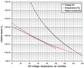
Image: Physik Instrumente (PI)
The friction interface: where life is determined
An ultrasonic piezo motor converts stator vibration into linear or rotary motion through frictional contact. The stator's tip (or contact pad) presses against a runner (linear) or rotor (rotary) with a controlled preload force, typically 0.5 to 10 N depending on motor size. The ultrasonic vibration at the tip creates an elliptical motion (driven at the stator's resonant frequency) that "walks" along the runner surface.
This contact is not sliding in the conventional sense. The tip engages the runner surface briefly during each vibration cycle (at 40 kHz, this is 25 µs per cycle), applies a tangential force, then lifts off. But the contact is not perfectly clean. Micro-slip occurs at the interface edges, asperities collide, and material is removed at the atomic and particle level. Over billions of contact cycles, this wear accumulates.
Materials at the interface
The friction tip is almost universally a hard ceramic: alumina (Al₂O₃), zirconia (ZrO₂), silicon nitride (Si₃N₄), or occasionally a composite. The runner surface varies more widely:
- Alumina strip or coating on an aluminium or steel bar (common in linear motors)
- Hard-anodized aluminium (Al₂O₃ layer, 25 to 50 µm thick, on 6061 or 7075 aluminium)
- Nickel boride or chromium plating on steel
- Silicon nitride or silicon carbide ceramic strips
- Diamond-like carbon (DLC) coatings on metal substrates
The choice of materials pairing determines wear rate, friction coefficient, and the nature of the wear debris. Not all pairings are equal. Alumina-on-alumina is well-characterized and reliable but produces relatively high wear. Alumina-on-DLC offers 3 to 10 times lower wear but at higher cost. Silicon nitride pairings offer good wear resistance and chemical stability.
Wear mechanisms at the micro scale
Three wear mechanisms operate simultaneously at the friction interface:
-
Adhesive wear. At contact points, momentary bonding occurs between asperities on the tip and runner. When the tip separates, material transfers from one surface to the other. This mechanism dominates when surfaces are clean and smooth.
-
Abrasive wear. Hard particles (either from the interface materials themselves or from external contamination) plough grooves in the softer surface. Loose wear debris recirculates at the interface, acting as an abrasive medium. This mechanism accelerates over time as debris accumulates, creating a self-reinforcing degradation cycle.
-
Tribochemical (corrosive) wear. In humid environments, water molecules at the contact promote chemical reactions that form softer surface layers (e.g., aluminium hydroxide on alumina). These layers are then mechanically removed. This mechanism is significant for alumina above 40% relative humidity and can increase wear rates by a factor of 2 to 5 compared to dry conditions.
The Archard wear equation applied to piezo motors
Wear volume can be estimated using the Archard equation:
V = k × F × d
where V is the worn volume, k is the specific wear rate (mm³/N·m), F is the normal load (N), and d is the sliding distance (m).
Published specific wear rates for materials used in ultrasonic motors:
| Materials pairing | Specific wear rate k (mm³/N·m) | Conditions |
|---|---|---|
| Al₂O₃ on Al₂O₃ | 1 × 10⁻⁷ to 5 × 10⁻⁷ | Dry, 25 °C, 40 kHz |
| Al₂O₃ on hard-anodized Al | 5 × 10⁻⁷ to 2 × 10⁻⁶ | Dry, 25 °C |
| Si₃N₄ on Si₃N₄ | 5 × 10⁻⁸ to 2 × 10⁻⁷ | Dry, 25 °C |
| Al₂O₃ on DLC-coated steel | 1 × 10⁻⁸ to 5 × 10⁻⁸ | Dry, 25 °C |
| ZrO₂ on Al₂O₃ | 2 × 10⁻⁷ to 8 × 10⁻⁷ | Dry, 25 °C |
The "sliding distance" in a piezo motor context is the cumulative distance the tip moves relative to the runner surface. For a motor travelling at 10 mm/s, the sliding distance accumulates at 10 mm/s (or 36 m/hour, 864 m/day at 100% duty cycle).
Worked example: friction tip wear life
Motor parameters:
- Tip material: alumina
- Runner: alumina strip
- Preload: 2 N
- Average sliding velocity: 20 mm/s
- Duty cycle: 10%
- Specific wear rate: 3 × 10⁻⁷ mm³/N·m
Tip geometry: hemisphere with initial radius 1.0 mm. The motor fails when the tip has worn flat to a contact diameter of approximately 1.1 mm, corresponding to a spherical cap volume of approximately 0.07 mm³.
Effective sliding distance per day: 20 mm/s × 0.10 (duty cycle) × 86,400 s/day = 172.8 m/day
Worn volume per day: 3 × 10⁻⁷ mm³/N·m × 2 N × 172.8 m = 1.04 × 10⁻⁴ mm³/day
Life to failure: 0.07 mm³ / 1.04 × 10⁻⁴ mm³/day = 673 days ≈ 1.8 years
Total sliding distance at failure: 673 × 172.8 = 116,300 m ≈ 116 km
This calculation illustrates why duty cycle is the dominant variable. At 1% duty cycle (a typical intermittent positioning application), the same motor lasts 18 years. At 50% duty cycle (continuous scanning), it lasts 4 months.
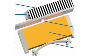
Image: Physik Instrumente (PI)
Ceramic fatigue in PZT stators
The PZT elements in the stator are subjected to cyclic mechanical stress at the resonant frequency. At 40 kHz, the PZT accumulates 3.5 × 10⁹ stress cycles per day of continuous operation. Ceramic fatigue is a real phenomenon in PZT, though it differs fundamentally from metal fatigue.
Mechanical fatigue
PZT is brittle; it does not yield plastically. Fatigue in PZT progresses through subcritical crack growth from pre-existing flaws (pores, grain boundaries, surface defects). The relevant parameter is the stress intensity factor range (ΔK) relative to the fracture toughness (K_IC). For PZT-8:
- K_IC ≈ 1.0 to 1.5 MPa·√m
- Maximum stress amplitude during motor operation: 5 to 30 MPa (depending on drive voltage and resonance amplitude)
- Corresponding ΔK for typical flaw sizes (10 to 50 µm): 0.05 to 0.3 MPa·√m
Since ΔK is well below K_IC, mechanical fatigue crack growth is extremely slow. Published fatigue data for PZT shows endurance limits exceeding 10¹⁰ cycles at stress amplitudes below 30 MPa. This means that mechanical fatigue is not a practical life limiter for properly designed ultrasonic motors; the friction interface will always wear out first.
Electrical fatigue (domain degradation)
A more insidious fatigue mechanism occurs at the domain level. Repeated AC cycling causes gradual domain wall pinning and de-aging of the piezoelectric response. The manifestations are:
- A slow decrease in the piezoelectric coefficient d₃₃ (0.5 to 2% per decade of time at elevated drive levels).
- A gradual shift in the electrical impedance spectrum.
- An increase in dielectric losses (tan δ), which increases self-heating, which accelerates domain degradation.
This degradation is logarithmic in time, meaning most of the change occurs early, then slows. For hard PZT compositions driven within their rated voltage range, the total degradation over 10 years of continuous operation is typically 5 to 10%. This reduces motor force and velocity by a similar percentage, which is usually within the system's operating margin.
Driving PZT above its rated field strength (typically 500 to 1000 V/mm for hard compositions) accelerates electrical fatigue dramatically. This is one reason why motor manufacturers specify maximum drive voltage carefully.
Adhesive bond fatigue
The epoxy or solder bond between PZT and the metal stator body is subjected to shear stress at every vibration cycle. Epoxy bonds have finite fatigue lives; typical structural epoxies fail after 10⁷ to 10⁹ cycles at moderate stress amplitudes. Since a 40 kHz motor accumulates 10⁹ cycles in roughly 7 hours, adhesive bond fatigue is a legitimate concern.
Mitigation strategies:
- Minimize bond-line thickness. Thin bonds (< 25 µm) are stiffer and more fatigue-resistant than thick bonds.
- Use high-fatigue-life adhesives. Certain epoxies (e.g., Hysol EA 9394, Araldite AV138) are formulated for fatigue resistance.
- Solder bonding. For high-reliability applications, solder bonding (using a tin-based solder with a compatible metallization on the PZT) provides a metallic bond with effectively infinite fatigue life under normal conditions. The downside is the higher process temperature, which can cause partial depolarization if not managed carefully.
- Active solder (e.g., S-Bond). These solders contain reactive elements (titanium, zirconium) that bond directly to ceramics without metallization, simplifying the process.
How duty cycle affects life
Duty cycle is the fraction of time the motor is actively moving (stator vibrating, tip in sliding contact with the runner). It is the single most important parameter for predicting motor life, because:
- Friction wear is directly proportional to cumulative sliding distance, which scales with duty cycle.
- PZT fatigue cycles accumulate proportionally to duty cycle.
- Self-heating scales with duty cycle, and elevated temperature accelerates all degradation mechanisms.
Duty cycle categories and typical life expectations
| Application type | Typical duty cycle | Expected life |
|---|---|---|
| Intermittent positioning (pick-and-place, valve actuation) | 0.1 to 1% | 10 to 20+ years |
| Periodic adjustment (optics alignment, antenna pointing) | 1 to 5% | 5 to 15 years |
| Frequent scanning (inspection, metrology) | 5 to 20% | 2 to 10 years |
| Continuous scanning (printing, machining) | 20 to 50% | 6 months to 3 years |
| Continuous rotation (conveyor, wheel drive) | 50 to 100% | 3 to 12 months |
These are order-of-magnitude estimates for well-designed motors with alumina friction interfaces. Actual life depends on preload, velocity, environment, and materials.
The self-locking advantage
A key feature of ultrasonic piezo motors is passive self-locking: when the drive signal is removed, the friction interface acts as a brake, holding the position without power or heat generation. This means that in positioning applications, the motor only needs to run during the brief moments of motion, then locks in place. An autofocus lens motor, for example, might move for 200 ms to focus, then hold for 30 s until the next focus event, yielding a duty cycle of 0.7%. This is why piezo motors in consumer cameras last the lifetime of the product despite having friction interfaces.
Accelerated life testing
Validating motor lifetime of 10+ years through real-time testing is impractical. Accelerated life tests (ALT) compress the test duration by increasing the severity of operating conditions, then extrapolating to normal conditions using physics-based models.
Common acceleration methods
Increased duty cycle. The simplest acceleration method: run the motor at 100% duty cycle instead of the application's 5%. This compresses a 20-year life into 1 year of testing. The assumption is that wear rate per unit sliding distance is constant, which holds approximately for friction wear but may underestimate adhesive bond fatigue at elevated temperature.
Increased preload. Doubling the preload approximately doubles the wear rate per the Archard equation. A 2x acceleration factor from preload combined with 20x from duty cycle gives 40x total, compressing 20 years into 6 months.
Elevated temperature. Running at 80 °C instead of 25 °C accelerates adhesive degradation and PZT aging. The Arrhenius acceleration factor is typically 2 to 4x per 30 °C increase for adhesive bond degradation.
Increased drive voltage. Driving at 120% of rated voltage increases vibration amplitude, contact forces, and PZT stress simultaneously. This accelerates multiple failure modes but can introduce failure modes not present at normal conditions, making extrapolation less reliable.
Test protocols
A robust ALT protocol for ultrasonic piezo motors includes:
- Baseline characterization. Measure motor force, velocity, no-load speed, resonant frequency, and impedance at the start.
- Periodic performance checks. Interrupt the test every 100 to 1000 hours to re-measure baseline parameters. Plotting force and velocity versus accumulated sliding distance reveals the degradation trajectory.
- Failure criteria. Define failure as a specific performance threshold: for example, force drops below 70% of initial, or velocity drops below 50% of initial.
- Post-mortem analysis. After failure, examine the friction interface under optical and electron microscopy. Measure tip wear dimensions. Analyze wear debris composition and particle size distribution. Check PZT polarization level and bond integrity.
- Statistical treatment. Test at least 5 to 10 units to capture unit-to-unit variation. Fit lifetime data to a Weibull distribution to estimate B10 and B50 lives.
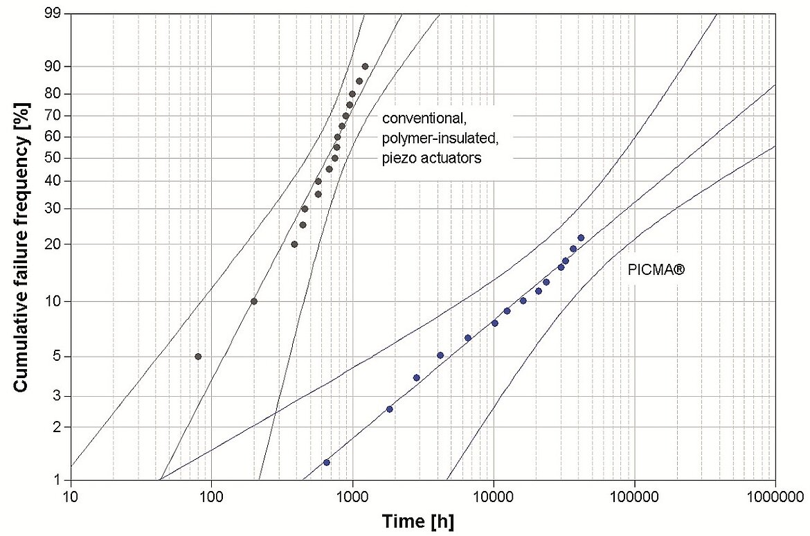
Image: Weibull lifetime analysis from accelerated life testing. Conventional polymer-insulated piezo actuators reach 50% cumulative failures within roughly 1,000 hours, while PICMA ceramic-insulated actuators show failures beginning only after 10,000 hours under the same stress conditions. The Weibull plot format is the standard tool for extracting B10 and B50 life estimates from ALT data. Source: Physik Instrumente (PI)
Interpreting ALT results
A typical ALT result for an alumina-on-alumina ultrasonic linear motor might look like this:
- 10 units tested at 100% duty cycle, 2 N preload, 20 mm/s velocity, 25 °C
- Median sliding distance to 70% force retention: 85 km
- B10 life (10% failure probability): 52 km
- Weibull shape parameter β: 2.8 (indicating wear-out failure mode)
For an application at 5% duty cycle and 10 mm/s average velocity:
- Sliding distance per year: 10 mm/s × 0.05 × 3.15 × 10⁷ s/year = 15,750 m/year = 15.75 km/year
- Median life: 85 / 15.75 = 5.4 years
- B10 life: 52 / 15.75 = 3.3 years
If the application requires 10-year B10 life, the design must be modified: lower preload, better materials (DLC coating), or lower duty cycle.
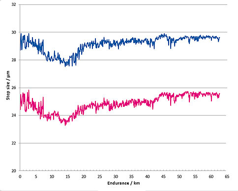
Image: Endurance run data for the PICMAWalk piezo linear motor. Step size (in µm) for two units remains stable across 65 km of cumulative travel, demonstrating consistent friction interface performance. Source: Physik Instrumente (PI)
Wear debris and contamination
Particle characteristics
Wear debris from ultrasonic motor friction interfaces consists primarily of sub-micrometre to micrometre-scale particles of the interface materials. For alumina-on-alumina:
- Median particle size: 0.2 to 2 µm
- Size distribution: log-normal, with a tail extending to 10 µm
- Composition: α-Al₂O₃ (the original crystal phase), sometimes with amorphous alumina from tribochemical reactions
- Morphology: irregular, angular fragments (from mechanical wear) and platelets (from tribochemical wear)
Contamination implications
In cleanroom and vacuum environments, wear debris is a contamination source. The generation rate can be estimated from the Archard equation: if the specific wear rate is 3 × 10⁻⁷ mm³/N·m and the preload is 2 N, then 6 × 10⁻⁷ mm³ of debris is produced per metre of sliding distance, or 6 × 10⁻⁴ mm³ per kilometre. Assuming particle density of 3.9 g/cm³ (alumina) and average particle diameter of 1 µm, the volume of a single spherical particle is approximately 5.2 × 10⁻¹⁰ mm³, giving roughly 10⁶ particles per kilometre of travel.
In practice, most particles remain trapped at the friction interface or in adjacent grooves. Particle capture strategies (discussed in the vacuum and cleanroom article) can contain 90 to 99% of generated debris, reducing the released particle count to 10⁴ or fewer per kilometre.
Wear debris feedback loop
Accumulated wear debris at the friction interface changes the contact conditions. Loose particles:
- Increase the effective surface roughness, potentially increasing friction and wear rate.
- Can embed in the softer surface, creating hard asperities that plough the opposing surface.
- In severe cases, can separate the tip from the runner, reducing contact stiffness and motor force.
Periodic cleaning of the friction interface (where accessible) can reset this degradation mechanism. Some motor designs incorporate self-cleaning features, such as grooves in the runner that channel debris away from the active contact zone.
Secondary failure modes
While friction interface wear dominates, other failure modes can limit motor life in specific circumstances.
Lead wire fatigue
The fine wires connecting the drive electronics to the PZT electrodes are subjected to vibration at the motor's resonant frequency. If the wire is not adequately strain-relieved, it can fatigue-fracture within months. This is a design and assembly quality issue rather than an inherent limitation; proper strain relief and flexible wire materials (e.g., litz wire, beryllium copper ribbon) effectively eliminate it.
Preload spring relaxation
The preload mechanism (usually a leaf spring or coil spring) maintains constant contact force between the stator tip and runner. If the spring material stress-relaxes over time (particularly at elevated temperatures), preload decreases, and motor performance degrades. Stainless steel springs operating below 30% of yield stress maintain preload indefinitely at room temperature. At elevated temperatures, spring relaxation becomes a concern; beryllium copper or Inconel springs offer better high-temperature stability.
Electrical failure
Drive electronics failure (capacitor aging, solder joint fatigue, semiconductor degradation) can end the system's useful life before the motor itself wears out. This is outside the scope of motor life prediction but is worth noting: in many fielded systems, electronics reliability limits the system's mean time between failures rather than motor wear.
Stator crack
Manufacturing defects (porosity, machining damage, residual stress from poling) can create sites for crack initiation in the PZT or in the stator body. Cracks grow slowly under cyclic loading and eventually cause catastrophic stator fracture. This failure mode is rare in production motors (< 0.1% failure rate) but is the primary infant mortality mechanism. Quality control through impedance testing and visual inspection screens out most defective units.
Practical guidelines for maximizing motor life
-
Specify the minimum preload that meets force requirements. Every additional newton of preload costs sliding life proportionally.
-
Minimize duty cycle through system design. Use the motor's self-locking property. Move fast, settle, lock. Avoid dithering or continuous position-holding with the motor energized.
-
Select the best affordable materials pairing. If the application requires long life at high duty cycles, invest in DLC-coated runners or silicon nitride interfaces. The 5 to 10x life improvement justifies the higher component cost in most cases.
-
Control the thermal environment. Every 20 °C of unnecessary temperature rise roughly halves adhesive bond life and accelerates PZT aging. Provide thermal paths and limit duty cycle to control stator temperature.
-
Implement health monitoring. Track the motor's resonant frequency, impedance, and force output over time. Gradual shifts indicate wear progression. A sudden change in resonant frequency or impedance may indicate a crack or bond failure, warranting replacement before catastrophic failure.
-
Design for tip replacement. In high-wear applications, design the motor assembly so the friction tip can be replaced as a wear part, analogous to replacing brake pads. This extends system life indefinitely at the cost of periodic maintenance.
-
Protect the friction interface from contamination. External particles (dust, metal chips, process residues) at the friction interface accelerate wear dramatically. Enclose the interface or use protective bellows in dirty environments.
-
Validate life expectations with ALT. Never rely solely on calculations. The Archard equation provides a starting estimate, but real-world factors (surface finish variation, humidity, contamination, assembly variability) can shift actual life by factors of 2 to 5 from predictions.
Life expectations across application domains
To provide practical context, here are representative life expectations for common applications:
Camera autofocus motor: 200,000 to 500,000 focus cycles. At 5 mm travel per cycle and 0.1 s per cycle, this corresponds to roughly 1 to 2.5 km of total sliding distance and 6 to 14 hours of cumulative motor-on time. Limited by tip wear but always outlasts the product's useful life.
Semiconductor wafer positioning stage: 5 to 10 years at 5 to 10% duty cycle. The motor accumulates 50 to 150 km of sliding distance. Alumina-on-DLC interfaces are used to meet this requirement. Tip replacement may be scheduled at 5-year intervals.
Optical mirror adjustment (astronomy, beamline): 15 to 20 years at < 1% duty cycle. Total sliding distance under 20 km. Standard alumina interfaces are sufficient. The motor often outlasts the instrument.
Industrial valve actuator: 10 million to 50 million open/close cycles. At 10 mm per cycle, this is 100 to 500 km of sliding distance, typically accumulated over 10 to 20 years at 1 cycle per minute average. Requires a robust materials pairing and periodic maintenance.
Robotic joint drive: 1 to 5 years at 10 to 30% duty cycle. Accumulated distance of 50 to 500 km. One of the more demanding applications; DLC or silicon nitride interfaces recommended.
Summary
Ultrasonic piezo motor life is dominated by friction interface wear, a predictable mechanism that follows the Archard equation and scales linearly with preload and cumulative sliding distance. For typical intermittent positioning applications (duty cycles below 5%), motor life exceeds 10 years with standard materials. Higher duty cycles demand better materials, thermal management, and health monitoring. Ceramic fatigue and adhesive bond fatigue are secondary concerns for well-designed motors operating within rated conditions. Accelerated life testing, using increased duty cycle and preload as the primary acceleration factors, provides reliable lifetime predictions that can be validated in 3 to 12 months of testing. The key engineering lesson: in piezo motor design, every decision about preload, duty cycle, materials, and temperature has a direct, quantifiable impact on service life.