Technology
Piezo vs. servo motor: when direct drive stops making sense
Force density, resolution floors, bearing overhead, and the crossover point where ultrasonic piezo motors outperform electromagnetic servos
Piezo vs. Servo Motor: When Direct Drive Stops Making Sense
Servo motors have dominated precision motion control for decades. They are well understood, widely available, and supported by a deep ecosystem of drives, controllers, encoders, and mechanical components. When an engineer needs to move something with precision, a servo motor is the default starting point.
But defaults can be expensive. Below certain speed thresholds, below certain resolution limits, and above certain environmental constraints, servo motors carry overhead that ultrasonic piezoelectric motors simply do not. The ball screw, the coupling, the gearbox, the motor bearings, the lubrication schedule: each component adds cost, complexity, and error. In some applications, the overhead exceeds the benefit.
This article maps the boundary between the two technologies with specific numbers, real product data, and worked examples, so you can identify exactly when each technology makes engineering sense.
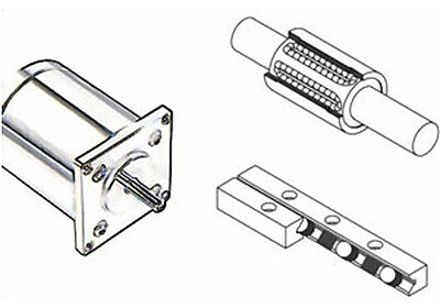
Image: Key components of a servo motor linear axis: rotary motor, ball screw assembly, and linear guide bearing. Source: Physik Instrumente (PI)
| Parameter | Piezoelectric | Servo Motor |
|---|---|---|
| Resolution | 0.5 nm | 100 nm-1 um |
| Bandwidth | 1-5 kHz | 100-500 Hz |
| Stiffness | Low | High |
| Force Range | 0.5-20 N | 1-500 N |
| Vacuum Compatibility | Excellent | Moderate |
| Size | Compact | Larger |
| Cost per Axis | $$$ | $$ |
| Settling Time | <1 ms | 5-50 ms |
Fundamental Operating Principles
Electromagnetic Servo Motors
A servo motor (brushless DC or permanent magnet synchronous) produces torque through the interaction of a rotating magnetic field from stator coils with permanent magnets on the rotor. Torque is proportional to current. Speed is proportional to voltage, minus the back-EMF. The motor output is rotary; conversion to linear motion requires a ball screw, lead screw, belt, rack-and-pinion, or linear motor architecture.
Direct-drive rotary servos eliminate the gearbox by using large-diameter, high-pole-count motors that produce high torque at low speed. Direct-drive linear servos, available in both ironless and iron-core configurations, skip the rotary-to-linear conversion entirely. Iron-core linear motors (such as the Parker MX80L series, capable of 2,000 mm/s) offer high force density but introduce cogging forces from the interaction between iron teeth and magnets. Ironless designs (such as the Aerotech ABL1000 or PI V-551) eliminate cogging entirely but sacrifice some force density.
Ultrasonic Piezoelectric Motors
Ultrasonic piezo motors convert high-frequency vibration (20 to 200 kHz) of a piezoelectric element into continuous macroscopic motion through friction coupling at a contact interface. The most common designs are traveling-wave rotary motors, standing-wave linear motors (often called "stick-slip" or "inertia drive" types), and resonant-bar linear motors. A detailed explanation of how ultrasonic piezoelectric motors work covers the resonance conditions and stator geometry that make this possible.
The key distinction: piezo motors use friction as the drive mechanism. A piezo element vibrates ultrasonically, and a preloaded contact tip or surface transfers that vibration into linear or rotary motion through carefully controlled stick-slip or elliptical motion at the contact point. Speed is controlled by vibration amplitude and frequency. Position is held passively by the same friction that enables motion, requiring zero electrical power.
Force and Torque Density
Servo motors have excellent force density when operated at their design speed. A 60 mm frame BLDC motor produces 0.5 to 2 Nm continuous torque at 3,000 RPM, delivering 150 to 600 W of mechanical power. Coupled with a precision ball screw (5 mm pitch, 90% efficiency), this translates to roughly 500 to 2,000 N of linear thrust at 250 mm/s.
At low speeds the picture changes. Servo motor torque is thermally limited at stall or near-stall conditions because the motor must sustain full current to produce holding torque. Without rotor-driven airflow, cooling capacity drops. A motor rated for 2 Nm continuous at speed may only sustain 1.5 Nm at stall.
Ultrasonic piezo motors produce force through preloaded friction contact, with typical values ranging from under 1 N for miniature devices (the Nanomotion Edge produces 0.35 N at just 0.55 g) up to 600 N for heavy-duty designs (the PI N-216 NEXLINE). Mid-range commercial motors cluster around 3.5 to 18 N: the Nanomotion HR4 delivers 15 to 18 N stall force, the PI N-310 NEXACT provides 10 N, and the SmarAct SLC-2430 achieves 3.5 N blocking force. These numbers are modest compared to servos. But force is independent of speed, and at zero speed, piezo motors hold position with full preload force and zero power consumption.
The force density comparison is therefore speed-dependent. At high speeds (above 50 mm/s), servos win decisively. At zero speed (holding), piezo motors win because they require zero power while servos require continuous stall current.
Specific Product Force Comparison
| Motor | Type | Peak/Stall Force | Continuous Force | Speed Range |
|---|---|---|---|---|
| PI V-551 | Direct-drive linear servo | 180 N peak | 27 N continuous | Up to 500 mm/s |
| Aerotech PRO165LM | Direct-drive linear servo | N/A (custom) | High (iron-core) | Up to 2,000 mm/s |
| Parker MX80L | Iron-core linear servo | High | High | Up to 2,000 mm/s |
| Anorad/Rockwell CHPS | Linear servo | Very high | High | Up to 6,000 mm/s, 25 g accel |
| Nanomotion HR4 | Ultrasonic piezo | 15 to 18 N stall | 8 to 12 N | Up to 250 mm/s |
| PI N-310 NEXACT | Ultrasonic piezo | 10 N | 5 to 7 N | Up to 10 mm/s |
| PI N-664 NEXACT | Ultrasonic piezo | 15 N holding | 8 to 10 N | Moderate |
| PI N-216 NEXLINE | Ultrasonic piezo | 600 N holding | 300+ N | Sub-mm/s |
| SmarAct SLC-2430 | Ultrasonic piezo | 3.5 N blocking | 1.5 to 2.5 N | >20 mm/s |
| Nanomotion Edge | Ultrasonic piezo | 0.35 N | 0.15 N | Up to 200 mm/s |
| New Scale M3-L | Ultrasonic piezo | ~1.5 N | ~0.5 N | Moderate |
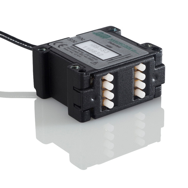
Image: Nanomotion HR8 ultrasonic motor element (15 to 18 N per motor, 250 mm/s). Multiple ceramic fingers provide scalable force output. Source: Nanomotion
Worked Example: Force Budget for a Wafer Inspection Z-Axis
An inspection system requires a 25 mm travel vertical axis carrying a 500 g optics assembly (4.9 N gravity). The axis moves at 0.5 mm/s during scanning, repositions at 10 mm/s between fields of view, and holds for 5 seconds at each measurement point. Cycle time is critical; the axis performs 200 move-and-measure cycles per hour.
Servo approach: A 42 mm frame BLDC motor with 10 mm pitch ball screw delivers 300 N continuous force, far exceeding the 4.9 N gravity load. However, the motor draws 15 to 20 W continuously, even during hold, because current is required to maintain torque against gravity. Over an 8-hour shift: 120 to 160 Wh of heat deposited into the stage assembly. The ball screw adds friction (1 to 3 N) that the motor must also overcome, increasing power draw. Motor case temperature reaches 50 to 70 degrees C.
Piezo motor approach: A stick-slip piezo motor (such as the PI N-310 NEXACT with 10 N force and 20 mm travel) handles the 500 g payload. With a constant-force spring providing 4.5 N of gravity compensation, the motor only needs to produce 0.4 N for vertical motion plus dynamic forces. During hold, the friction preload supports the remaining 0.4 N with zero power. During scanning at 0.5 mm/s, power draw is 1 to 2 W. Over 8 hours, total energy: approximately 5 to 15 Wh. Motor temperature rise: less than 5 degrees C.
The piezo approach uses 10x to 30x less energy and introduces negligible thermal perturbation, which directly benefits measurement accuracy. The tradeoff: the repositioning speed of 10 mm/s is near the PI N-310's practical limit, so the slew portion may take slightly longer. If the application can tolerate 0.5 to 1 second longer cycle times, the piezo motor is the better system choice.
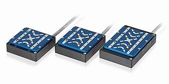
Image: PI PIMag direct-drive linear stages (V-522, V-524, V-528) with ironless linear motor and crossed-roller bearings. Source: Physik Instrumente (PI)
Speed Regimes and the Crossover Zone
This is the most important selection criterion. Servo motors and piezo motors operate in fundamentally different speed regimes, and understanding the overlap zone determines which technology fits a given application.
Servo motors are designed for continuous operation at hundreds to thousands of RPM. Translated to linear motion via a 5 mm pitch ball screw, this corresponds to 10 to 500 mm/s. Direct-drive linear servos achieve 0.5 to 6 m/s (the Anorad/Rockwell CHPS reaches 6 m/s with 25 g acceleration). Servos are at their best when moving fast and can operate continuously at rated speed indefinitely.
Ultrasonic piezo motors typically operate at 0.5 to 250 mm/s for linear types. The PI U-521 PILine reaches 200 mm/s with 18 mm travel and 1 nm resolution. The Nanomotion HR4 reaches 250 mm/s. Some specialized designs push higher: the Xeryon XLS achieves 1,000 mm/s, which overlaps substantially with servo territory. At the slow end, the PI N-310 NEXACT operates at up to 10 mm/s, optimized for maximum resolution rather than speed. The SmarAct SLC-2430 sits in the middle at over 20 mm/s.
The speed limitation is fundamental. The friction contact interface cannot sustain the high relative velocities that electromagnetic motors achieve without excessive wear. Designs that push speed (like the Xeryon XLS) typically sacrifice force density or lifetime to achieve it.
Speed-Application Map
| Speed Regime | Typical Applications | Preferred Technology | Key Products |
|---|---|---|---|
| 0 to 0.01 mm/s | Nanopositioning, interferometric alignment | Piezo | PI N-664 NEXACT (0.03 nm OL resolution) |
| 0.01 to 1 mm/s | Scanning probe microscopy, fiber alignment | Piezo | SmarAct SLC-2430 (1 nm CL), PI N-310 |
| 1 to 10 mm/s | Optical inspection, metrology scanning | Piezo or servo | Crossover zone; depends on resolution |
| 10 to 50 mm/s | Wafer probing, component placement | Servo (or fast piezo) | PI U-521 PILine (200 mm/s capable) |
| 50 to 200 mm/s | Pick-and-place, PCB inspection | Servo | Newport IMS (DC servo, ball screw) |
| 200 to 1,000 mm/s | Packaging, labeling, general automation | Servo | Parker MX80L (2,000 mm/s), PI V-551 (500 mm/s) |
| > 1,000 mm/s | High-speed scanning, laser machining | Direct-drive linear servo | Anorad/Rockwell CHPS (6,000 mm/s) |
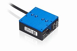
Image: PI U-521 PILine ultrasonic motor stage (18 mm travel, 200 mm/s, 1 nm resolution). Source: Physik Instrumente (PI)
If your application requires sustained speeds above 100 mm/s, a servo motor is almost always the right choice. If your application involves slow, precise positioning (below 20 mm/s) with extended hold times, the piezo motor becomes competitive. The Xeryon XLS is a notable exception that challenges this boundary, reaching 1,000 mm/s at a price point (under 250 euros) that undercuts comparable voice coil actuators (under 500 euros).
Resolution and Minimum Incremental Motion
This is where piezo motors often justify their higher per-unit cost. The resolution advantage is not about the sensor; it is about the absence of mechanical transmission errors.
A servo motor's minimum step size depends on the encoder resolution and the mechanical drivetrain. Consider a typical high-precision linear axis:
- Servo motor with 20-bit encoder (1,048,576 counts per revolution)
- Ball screw with 5 mm pitch
- Minimum theoretical step: 5 mm / 1,048,576 = 4.8 nm
That 4.8 nm figure looks impressive on paper. In practice, several factors degrade it:
- Ball screw backlash: Even precision-ground, preloaded ball screws have 1 to 3 micrometers of reversal error. Anti-backlash designs reduce this to 0.5 to 1 micrometer but add friction and cost.
- Ball screw pitch error: +/- 3 to +/- 5 micrometers per 300 mm for precision-ground screws. Error mapping in the controller can compensate to +/- 1 micrometer, but residual periodic error remains.
- Coupling compliance: Flexible couplings between motor and screw introduce angular play and torsional compliance, adding 0.5 to 2 micrometers of positioning uncertainty.
- Bearing runout: Ball screw support bearings contribute 1 to 5 micrometers of axial error.
The practical minimum incremental motion (MIM) of a ball screw servo axis is 0.5 to 5 micrometers for high-quality assemblies. Achieving sub-micrometer positioning requires an external linear encoder (bypassing the ball screw errors), which adds $500 to $2,000 to the system cost.
Ultrasonic piezo linear motors drive the load directly, with no ball screw, coupling, or gear reducer. With a high-resolution linear encoder, minimum incremental motion of 5 to 50 nm is routine. The best commercial examples push dramatically lower: the PI N-664 NEXACT achieves 0.03 nm in open-loop and 2 nm MIM in closed-loop with a 30 mm travel range. The PI V-551 (a direct-drive linear servo, for comparison) offers 0.2 nm encoder resolution. The Aerotech ABL1000 achieves 0.5 nm closed-loop resolution with air bearings.
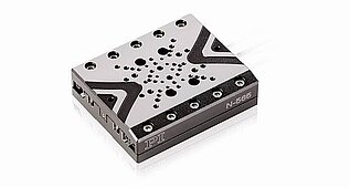
Image: PI N-565 NEXACT PiezoWalk stage (up to 52 mm travel, 0.5 nm resolution, self-locking at rest). The chevron pattern on the top plate is the monolithic flexure guidance. Source: Physik Instrumente (PI)
Resolution Comparison with Encoder Options
| Actuator | Encoder Type | Encoder Resolution | Practical System MIM | Bidirectional Repeatability |
|---|---|---|---|---|
| Servo + ball screw | Rotary, 13-bit | 0.6 um (at 5 mm pitch) | 5 to 20 um | 5 to 25 um |
| Servo + ball screw | Rotary, 17-bit | 38 nm (at 5 mm pitch) | 2 to 10 um | 3 to 15 um |
| Servo + ball screw | Rotary, 20-bit | 4.8 nm (at 5 mm pitch) | 0.5 to 5 um | 1 to 10 um |
| Servo + ball screw | Linear, 1 um (Renishaw) | 1 um | 0.5 to 2 um | 0.5 to 3 um |
| Servo + ball screw | Linear, 0.1 um | 100 nm | 0.2 to 1 um | 0.3 to 2 um |
| Servo + ball screw | Linear, 1 nm (Renishaw ATOM DX) | 1 nm | 0.1 to 0.5 um | 0.2 to 1 um |
| Piezo motor (direct drive) | Linear, 1 um | 1 um | 0.5 to 1 um | 0.2 to 0.5 um |
| Piezo motor (direct drive) | Linear, 0.1 um | 100 nm | 20 to 100 nm | 50 to 200 nm |
| Piezo motor (direct drive) | Linear, 1 nm | 1 nm | 1 to 10 nm | 5 to 50 nm |
| Piezo motor (direct drive) | Linear, 0.1 nm | 0.1 nm | 0.5 to 5 nm | 2 to 20 nm |
| Direct-drive linear servo (PI V-551) | Linear, 0.2 nm | 0.2 nm | 1 to 10 nm | 5 to 50 nm |
| Direct-drive linear servo (Aerotech ABL1000) | Linear, 0.5 nm | 0.5 nm | 5 to 50 nm | 10 to 100 nm |
Critical insight: with the same 1 nm encoder (such as the Renishaw ATOM DX, which offers 2.5 nm resolution and supports speeds up to 20 m/s), a servo-plus-ball-screw system achieves 0.1 to 0.5 micrometer MIM limited by mechanical transmission errors, while a piezo motor achieves 1 to 10 nm MIM limited by friction dynamics and encoder noise. The actuator, not the encoder, is the limiting factor for the servo system. For the piezo motor, the encoder is closer to being the limiting factor, meaning resolution scales more directly with sensor quality.
Backlash and Reversal Error
Backlash is the position error that occurs when reversing direction. It is the single largest source of bidirectional positioning error in servo-driven systems and arguably the strongest argument for piezo motors in precision applications.
Sources of Backlash in Servo Systems
A servo linear axis accumulates backlash from multiple components:
- Ball screw nut: 1 to 20 micrometers (standard), 0.5 to 3 micrometers (preloaded)
- Coupling: 0.5 to 5 arc-minutes angular backlash
- Gearbox (if present): 1 to 15 arc-minutes
- Belt drive (if present): 10 to 100 micrometers
Total bidirectional repeatability for a well-built servo axis is typically 0.5 to 5 micrometers. Achieving sub-micrometer bidirectional repeatability requires either a direct-drive linear servo (eliminating the ball screw) or a secondary piezo fine-positioning stage.
Backlash Analysis by Gearbox Type
When a servo motor requires a gear reducer for higher torque at lower speed, the gearbox becomes an additional backlash source. The following table compares common gearbox types:
| Gearbox Type | Ratio Range | Backlash (arc-min) | Backlash at Ball Screw (um) | Cost Range | Efficiency |
|---|---|---|---|---|---|
| Spur gear, standard | 3:1 to 100:1 | 5 to 15 | 7 to 22 (at 5 mm pitch) | $50 to $300 | 85% to 95% |
| Spur gear, anti-backlash | 3:1 to 50:1 | 1 to 5 | 1.5 to 7 | $150 to $600 | 80% to 90% |
| Planetary, standard | 3:1 to 100:1 | 3 to 10 | 4 to 15 | $200 to $800 | 85% to 95% |
| Planetary, precision | 3:1 to 100:1 | 1 to 3 | 1.5 to 4.5 | $500 to $2,000 | 85% to 92% |
| Harmonic drive | 30:1 to 320:1 | 0.5 to 2 | 0.7 to 3 | $800 to $3,000 | 65% to 85% |
| Cycloidal | 6:1 to 120:1 | 0.5 to 1 | 0.7 to 1.5 | $600 to $2,500 | 75% to 90% |
| Strain wave (zero-backlash) | 50:1 to 160:1 | < 0.5 | < 0.7 | $1,500 to $5,000 | 60% to 80% |
The backlash at the ball screw output is calculated as: backlash_linear = (backlash_angular / 360) x screw_pitch x (1 / gear_ratio). For a 5 mm pitch screw, 1 arc-minute of gearbox backlash translates to approximately 1.45 micrometers of linear backlash before the gear ratio reduction.
Worked example: A 10:1 planetary gearbox with 3 arc-minutes of backlash, driving a 5 mm pitch ball screw. Linear backlash from the gearbox alone: (3 / 21,600) x 5,000 / 10 = 0.07 micrometers from the gearbox. But the ball screw's own backlash (1 to 3 micrometers for a preloaded nut) dominates. Total reversal error: 1 to 3.1 micrometers. Adding a harmonic drive (0.5 arc-minutes, 100:1 ratio) reduces gearbox contribution to negligible levels, but the ball screw nut remains the fundamental bottleneck. This illustrates why backlash reduction efforts in the gearbox often yield diminishing returns.
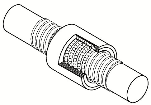
Image: Recirculating ball screw assembly cutaway. The balls circulating through the nut introduce backlash (1 to 3 um when preloaded) that limits bidirectional repeatability. Source: Physik Instrumente (PI)
Piezo Motor Reversal Behavior
Ultrasonic piezo motors have inherently zero backlash. The friction drive mechanism engages in both directions identically. Bidirectional repeatability is limited only by the encoder resolution and the controller's ability to manage the friction contact dynamics. The SmarAct SLC-2430 achieves 1 nm closed-loop resolution with sub-50 nm bidirectional repeatability. The PI V-551 (direct-drive servo) achieves +/- 0.05 micrometer repeatability with crossed-roller bearings.
Piezo motors do exhibit a reversal-related nonlinearity: the "dead zone" at direction reversal. When the drive signal reverses, the contact tip must overcome static friction before motion begins. This creates a small dead band (typically 10 to 100 nm) where commanded motion produces no output. Closed-loop control with a high-resolution encoder eliminates this dead band by detecting the stall and increasing drive amplitude until motion resumes. The dead band is orders of magnitude smaller than ball screw backlash and is fully correctable in the servo loop, making it a non-issue for most applications.
Bearing Technologies
The bearing system is often an overlooked cost and complexity driver. Servo motors require mechanical bearings both in the motor itself and in the drivetrain. A typical linear axis includes:
- Two motor bearings (preloaded angular contact or deep groove)
- Two to four ball screw support bearings
- A linear guide rail system (recirculating ball or roller bearings)
These bearings require lubrication (grease or oil), generate particles over time, have finite life (L10 ratings), and contribute to system stiffness and error budgets. In vacuum or cleanroom environments, bearing selection becomes a significant engineering challenge. Special greases, labyrinth seals, or magnetic preloading may be needed. For demanding vacuum and cleanroom operation, eliminating the ball screw also removes one of the principal particle and outgassing sources in the system.
Bearing Types in Precision Stages
Flexure bearings offer the ultimate in cleanliness and precision: frictionless, zero wear, zero particle generation, zero lubrication. However, they are limited to less than 1 mm of travel. Many miniature piezo stages (including PI NEXACT stages) use monolithic flexure mechanisms with zero maintenance requirements.
Crossed-roller bearings provide high stiffness and smooth motion over longer travel ranges. PI, Aerotech (ANT95L, ANT130L), and Dover use anti-creep cages to prevent roller skewing. The Aerotech ANT series achieves 0.5 nm MIM with crossed-roller guides.
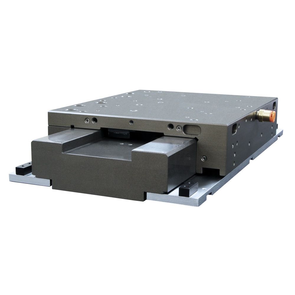
Image: Aerotech ABL1000 air bearing stage (0.5 nm closed-loop resolution, ironless linear motor, zero cogging). Source: Aerotech
Air bearings achieve the highest straightness (less than 0.1 micrometer per 100 mm for the Aerotech ABL1000) but require clean dry air supply and cost $20,000 to $50,000+ for a complete stage. They are standard in premium semiconductor inspection and lithography systems.
Ball bearings carry the highest loads but introduce 1 to 5 micrometers of axial error and require lubrication on a maintenance schedule. Standard for industrial servo axes, unsuitable for nanometer-class positioning.
Bearing Overhead Cost and Complexity Analysis
| Component | Servo Axis (50 mm travel) | Piezo Motor Stage (50 mm travel) |
|---|---|---|
| Motor bearings | 2x angular contact ($40 to $200) | None |
| Ball screw support bearings | 2x angular contact ($60 to $300) | None |
| Ball screw + nut assembly | 1x precision ground ($300 to $1,500) | None |
| Motor-to-screw coupling | 1x bellows or beam ($30 to $150) | None |
| Linear guide rails + blocks | 2x rails, 4x blocks ($200 to $800) | Integrated in stage ($0 incremental) |
| Lubrication system | Grease + maintenance interval | None (dry contact or flexure) |
| Total drivetrain component cost | $630 to $2,950 | $0 to $300 (crossed-roller guide) |
| Total drivetrain component count | 10 to 15 parts | 1 to 3 parts |
| Assembly labor (hours) | 4 to 8 | 0.5 to 1 |
| Maintenance interval | 2,000 to 10,000 hours | None (wear monitoring only) |
The piezo motor stage eliminates roughly $600 to $3,000 in drivetrain components and 3 to 7 hours of assembly labor. This cost savings partially offsets the higher unit cost of the piezo motor element. For small-volume production (1 to 100 units), the total system cost may favor the piezo approach once assembly labor and drivetrain components are included.
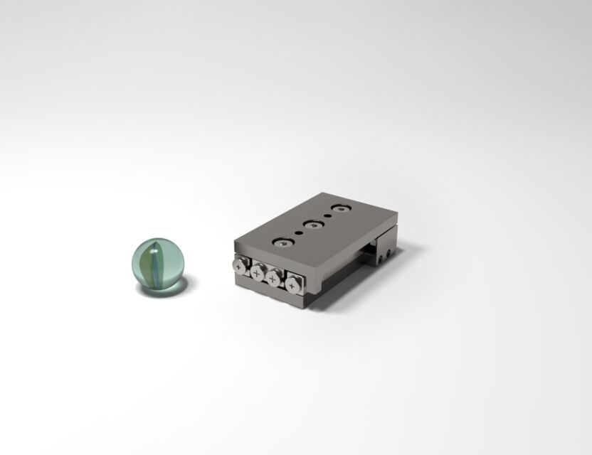
Image: SmarAct SLC-2445 miniature positioner (16 mm travel, 1 nm resolution, 36 g) shown next to a glass marble for scale. Source: SmarAct
Thermal Behavior and Power Dissipation
Thermal management is one of the most underappreciated factors in precision motion system design. Heat causes thermal expansion, which causes positioning error. In a metrology or semiconductor application, even a 0.1 degree C temperature change in a 100 mm aluminum stage produces 2.3 micrometers of thermal drift, enough to ruin nanometer-class measurements.
Servo Motor Thermal Profile
Servo motors dissipate power proportional to I squared R (copper losses) plus iron losses from eddy currents and hysteresis. This heat is continuous, speed-dependent, and present even at standstill.
At stall (zero speed, full holding force), a typical 60 mm frame BLDC servo dissipates 15 to 60 W. This is actually the worst thermal case because there is no forced convection from rotor motion. Halving the holding force reduces power to one quarter (due to the squared current relationship), but many applications require full force at hold.
A servo motor holding position in a precision stage exhibits a phenomenon called "servo dither": the controller continuously makes small corrections to maintain position, and each correction draws current. Even when the axis appears stationary, the motor dissipates 5 to 20 W in dither heating. Over hours of operation, this raises the stage temperature by 2 to 15 degrees C depending on thermal mass and cooling.
Direct-drive linear servos (like the PI V-551 with 27 N continuous force) have better thermal characteristics than ball screw servos because they eliminate the friction losses of the screw. However, they still require continuous current for force production, and the coils are often closer to the workpiece than a rotary motor would be, making thermal coupling worse.
The Aerotech PRO165LM addresses thermal effects through its ThermoComp technology, which uses real-time thermal modeling to compensate for thermally induced positional errors. This adds cost and complexity but can reduce thermal drift by 80% to 90%.
Piezo Motor Thermal Profile
Ultrasonic piezo motors consume power only during motion. At rest, the friction preload holds the position with zero power and zero heat generation. This is not a minor advantage; it is a fundamental physical difference.
During motion, piezo motors dissipate 1 to 8 W depending on speed and load. The heat is generated at the friction contact interface and in the piezoelectric element itself (dielectric losses). Because the power draw is low and intermittent, the thermal impact on the surrounding structure is minimal.
For applications with high duty cycles (moving more than 80% of the time), piezo motors can generate meaningful heat at the contact interface, but typical precision applications spend far more time holding than moving. A semiconductor inspection stage that moves for 2 seconds and holds for 5 seconds dissipates an average of 0.5 to 2 W, producing negligible thermal disturbance.
Thermal Impact on Measurement Accuracy
| Scenario | Servo Power at Hold | Piezo Power at Hold | Temperature Rise (100 mm Al stage) | Thermal Drift |
|---|---|---|---|---|
| Light load, intermittent | 10 to 20 W | 0 W | Servo: 1 to 3 C; Piezo: 0 C | Servo: 2.3 to 6.9 um; Piezo: 0 |
| Full load, continuous hold | 30 to 60 W | 0 W | Servo: 5 to 15 C; Piezo: 0 C | Servo: 11.5 to 34.5 um; Piezo: 0 |
| Active scanning, 50% duty | 15 to 40 W | 1 to 4 W | Servo: 3 to 8 C; Piezo: 0.2 to 0.8 C | Servo: 6.9 to 18.4 um; Piezo: 0.5 to 1.8 um |
In metrology applications where sub-micrometer accuracy is required, the thermal advantage of piezo motors is often the deciding factor. No amount of encoder resolution can compensate for a stage that is thermally drifting faster than the measurement cycle.
Control Architecture
Servo Motor Control
Servo motor control is a mature technology. A typical servo axis uses:
- Feedback sensor: Rotary encoder (13-bit to 20-bit) mounted on the motor shaft, or a linear encoder (such as the Renishaw ATOM DX with 2.5 nm resolution and 20 m/s maximum speed) mounted on the stage. Linear encoders bypass ball screw errors but add cost.
- Control loop rate: Typically 10 to 20 kHz for position loops, 40 to 100 kHz for current loops. Higher bandwidth enables faster settling and tighter tracking.
- Drive architecture: PWM current amplifiers with sinusoidal commutation for BLDC motors. Integrated drives (motor plus drive in one housing) are available from Aerotech, Parker, and others.
- Thermal compensation: The Aerotech ThermoComp system performs real-time thermal error correction. Other vendors rely on external temperature sensors and lookup tables.
Piezo Motor Control
Piezo motor control differs fundamentally from servo motor control because the drive signal is not a current command but a shaped waveform (typically ultrasonic) that controls the vibration mode of the piezoelectric element.
- Drive electronics: Ultrasonic frequency generators (20 to 200 kHz) with amplitude and frequency modulation. The PI E-727 digital piezo controller supports EtherCAT communication for integration into industrial automation networks.
- Feedback sensors: High-resolution linear encoders (optical or capacitive), capacitive displacement sensors, or strain gauges. Capacitive sensors achieve sub-nanometer resolution but are limited in range (typically less than 100 micrometers). For longer travel, optical linear encoders are standard.
- Control algorithms: Standard PID with feedforward is used for most applications. The friction-based drive mechanism introduces nonlinearity (especially at direction reversal), which requires careful tuning. Some controllers use adaptive algorithms that learn the friction characteristics of the specific motor.
- Settling behavior: Piezo motors can settle to final position in under 10 ms for small steps (PI reports less than 10 ms settling time for their 4-DOF piezo wafer stage, achieving less than 5 nm position stability). Servo motors with ball screws typically settle in 20 to 100 ms for similar precision, limited by mechanical compliance and backlash.
Integration Considerations
Servo motors benefit from decades of standardization. CANopen, EtherCAT, PROFINET, and other industrial protocols are universally supported. Piezo motor controllers are catching up (the PI E-727's EtherCAT support is a significant step), but the ecosystem is smaller. Engineers should verify that the piezo motor controller integrates with their existing motion platform before committing to the technology.
Cost Comparison by Precision Tier
The cost comparison depends heavily on the required performance level. At low precision, servos win on cost. At high precision, the mechanical overhead of servo systems drives cost above what piezo systems require.
Cost Breakdown by Precision Tier
| Precision Tier | Resolution | Servo System Components | Servo Total | Piezo System Components | Piezo Total |
|---|---|---|---|---|---|
| Standard (5 to 50 um) | 5 to 50 um | Motor ($150), drive ($200), screw ($200), guide ($150), encoder ($100), assembly ($200) | $1,000 | N/A (piezo overkill for this tier) | N/A |
| Precision (1 to 5 um) | 1 to 5 um | Motor ($300), drive ($400), precision screw ($600), guide ($300), 17-bit encoder ($300), assembly ($400) | $2,300 | Motor ($1,500), driver ($600), 1 um encoder ($300), stage ($800) | $3,200 |
| High Precision (0.1 to 1 um) | 0.1 to 1 um | Motor ($500), drive ($600), precision screw ($1,200), guide ($500), linear encoder ($800), anti-backlash ($400), assembly ($600) | $4,600 | Motor ($2,000), driver ($800), 0.1 um encoder ($600), stage ($1,200) | $4,600 |
| Ultra-precision (10 to 100 nm) | 10 to 100 nm | Motor ($800), drive ($1,000), precision screw ($2,000), air bearing ($3,000), linear encoder ($2,000), thermal mgmt ($500), assembly ($1,200) | $10,500 | Motor ($3,000), driver ($1,200), 1 nm encoder ($1,500), stage ($2,000) | $7,700 |
| Nanometer (1 to 10 nm) | 1 to 10 nm | Direct-drive linear motor ($5,000), drive ($2,000), air bearing ($5,000), interferometer ($5,000), thermal mgmt ($2,000), assembly ($2,000) | $21,000 | Motor ($4,000), driver ($1,500), 0.1 nm encoder ($3,000), stage ($3,000) | $11,500 |
The crossover point is around the "high precision" tier (0.1 to 1 micrometer resolution). Below that tier, servo systems are cheaper. Above that tier, piezo systems become progressively more cost-effective because the servo system requires increasingly expensive measures (air bearings, interferometers, thermal management) to compensate for drivetrain errors that the piezo system simply does not have.
A notable data point: the Xeryon XLS ultrasonic motor is available for under 250 euros, while an equivalent voice coil actuator costs under 500 euros. At the component level, piezo motors are competitive even before considering the drivetrain savings.
Total Cost of Ownership
The purchase price is only part of the story. Maintenance, energy, and downtime costs favor piezo motors in high-precision applications:
| Cost Factor | Servo Axis (per year) | Piezo Motor Stage (per year) |
|---|---|---|
| Energy (8 hr/day, 250 days) | $30 to $150 (15 to 80 W average) | $2 to $10 (1 to 5 W average) |
| Lubrication and maintenance | $100 to $500 (scheduled PM) | $0 to $50 (wear inspection) |
| Ball screw replacement (prorated) | $200 to $800 (3 to 5 year life) | N/A |
| Bearing replacement (prorated) | $50 to $200 | N/A |
| Calibration and backlash compensation | $200 to $500 | $50 to $200 |
| Estimated annual operating cost | $580 to $2,150 | $52 to $260 |
Over a 5-year life, the servo axis accumulates $2,900 to $10,750 in operating costs, while the piezo stage accumulates $260 to $1,300. This difference can easily exceed the higher purchase price of the piezo motor system, making piezo the lower total-cost-of-ownership choice in many precision applications.
The Crossover Point
Based on the analysis above, the crossover point where piezo motors become the better engineering choice occurs when the application meets most of these six criteria:
-
Required positioning resolution is below 1 micrometer. Once you cross below the 1 micrometer threshold, the mechanical transmission errors of a ball screw system dominate, and eliminating the ball screw (either via direct-drive servo or piezo motor) becomes necessary.
-
Maximum required speed is below 50 mm/s. Above this speed, servo motors are more efficient and durable. Below it, the speed limitation of piezo motors is not a penalty.
-
Bidirectional repeatability below 0.5 micrometer is required. Achieving this with a ball screw axis requires expensive anti-backlash measures. Piezo motors deliver it inherently.
-
Hold position with zero power is desirable. Any application with extended hold times (alignment fixtures, optical mounts, semiconductor inspection) benefits from the passive hold of piezo motors.
-
Magnetic field emission must be minimized. Servo motors contain permanent magnets and current-carrying coils that produce stray fields. Piezo motors have no magnetic components, assuming the encoder is optical or capacitive.
-
Operating environment is vacuum, cleanroom, or cryogenic. Piezo motors generate no heat at hold, produce no particles from brushes or commutation, and operate reliably at low temperatures. Eliminating the ball screw removes a major outgassing and particle source.
If your application hits three or more of these criteria, a piezo motor should be on your shortlist. If it hits five or six, the choice is nearly certain.
Application Decision Scenarios
Scenario 1: Semiconductor Mask Inspection Stage
Requirements: 300 mm x 300 mm travel, 50 nm bidirectional repeatability, 200 mm/s scanning speed, constant velocity within 0.01%, cleanroom Class 1, 24/7 operation. This class of application is examined further in the wafer stage positioning article.
Analysis: The 200 mm/s scanning speed exceeds most piezo motors' comfortable velocity range. The 300 mm travel is well within servo territory. The 50 nm repeatability requires either a direct-drive linear servo with air bearings and interferometric feedback, or a very high-end piezo system.
The constant velocity requirement of 0.01% is extremely demanding. A ball screw servo cannot achieve this; pitch error periodicity causes velocity ripple of 0.1% to 1%. A direct-drive linear servo with air bearings and laser interferometer can achieve 0.005% to 0.02% velocity constancy. A piezo motor at 200 mm/s is operating near its speed limit and cannot guarantee this velocity uniformity.
Recommendation: Direct-drive linear servo (such as an Aerotech ABL1000 with air bearings). The speed, travel, and velocity constancy requirements place this firmly in servo territory. Approximate cost: $40,000 to $100,000 per axis.
Scenario 2: Fiber Optic Alignment (6-DOF)
Requirements: 10 mm travel per axis (X, Y, Z), 5 nm resolution, 1 mm/s maximum speed, hold for 10 to 60 minutes during bonding cure, vacuum compatible (for some variants), 6 axes in a compact package, no magnetic fields (fiber Bragg grating sensor nearby).
Analysis: The 5 nm resolution eliminates ball screw servo axes (practical MIM of 0.5 to 5 micrometers). Direct-drive linear servos could achieve it but would produce magnetic fields (disqualified) and require continuous power during hold (thermal issue in vacuum). The 1 mm/s speed is well within piezo motor range. The extended hold times require zero-power position retention. The no-magnetics requirement disqualifies all electromagnetic motors.
Recommendation: Piezo motor, clearly. A 6-axis piezo motor stage (such as SmarAct SLC-based stages with 1 nm closed-loop resolution) with crossed-roller bearings and optical linear encoders meets all requirements. The zero-power hold avoids thermal perturbation during bonding. The absence of magnets protects the fiber sensor. Approximate cost: $15,000 to $30,000 for the 6-axis system.
Scenario 3: Automated Optical Inspection (AOI) XY Gantry
Requirements: 500 mm x 500 mm travel, 5 micrometer accuracy, 500 mm/s scan speed, 50 ms settling time, atmospheric pressure, 24/7 industrial operation, 5-year maintenance interval.
Analysis: The 500 mm/s scan speed and 500 mm travel are well beyond piezo motor capabilities. The 5 micrometer accuracy is easily achieved by a ball screw servo with a rotary encoder. The 50 ms settling time is routine for servo systems at this precision level. The 5-year maintenance interval is achievable with proper lubrication scheduling.
Recommendation: Servo motor, clearly. A pair of BLDC servo motors with precision ball screws and linear encoders (such as Newport IMS stages with 0.1 micrometer resolution via linear scale) provides the performance at the lowest cost. Approximate cost: $5,000 to $15,000 per axis.
Scenario 4: Cryo-Vacuum Positioning for Electron Microscopy
Requirements: 10 mm x 10 mm XY travel, 2 nm positioning resolution, operation at 77 K (liquid nitrogen temperature) and 10^-7 mbar vacuum, sample mass 50 g, minimal vibration, hold position during 30-minute imaging sessions, absolutely zero magnetic stray field (electron beam deflection sensitivity).
Analysis: This application hits all six crossover criteria. The cryogenic temperature eliminates most lubricants and causes differential thermal contraction in multi-material servo assemblies. Vacuum rules out any motor that relies on convective cooling. The 30-minute hold at zero power is essential because any heat source near the sample would cause thermal drift and ice contamination. The magnetic field requirement disqualifies all electromagnetic motors (even a small BLDC motor at 50 mm distance can produce 10 to 100 microtesla stray fields, enough to deflect an electron beam by nanometers).
Piezo motors operate in vacuum and at cryogenic temperatures because the piezoelectric effect is a bulk material property that persists across a wide temperature range. The friction interface may require modified preload to account for thermal contraction, and the friction coefficient changes at low temperatures, but commercial solutions exist (PI and SmarAct both offer cryo-compatible stages).
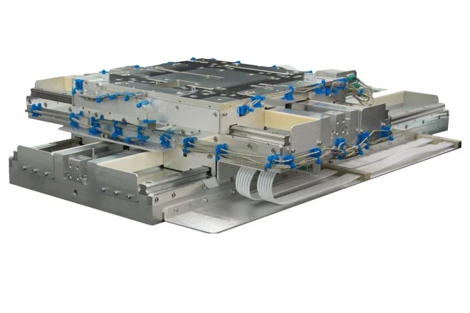
Image: Nanomotion ultra-precision XY vacuum stage. Piezo-driven stages operate in vacuum without lubricant outgassing or particle generation. Source: Nanomotion
Recommendation: Piezo motor, unambiguously. This is a textbook piezo application. A piezo XY stage with flexure guidance, capacitive feedback sensors, and ceramic construction provides 2 nm resolution at 77 K with zero magnetic emission and zero power at hold. No servo-based solution can meet the combined cryo, vacuum, magnetic, and thermal requirements. Approximate cost: $20,000 to $40,000 for the XY system.
Direct-Drive Linear Servos: The Middle Ground
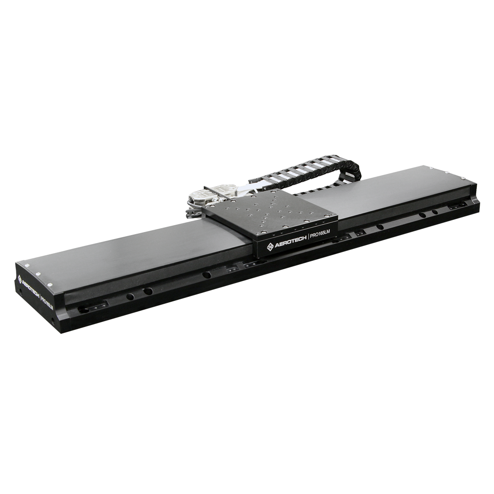
Image: Aerotech PRO165LM direct-drive linear motor stage (up to 1,500 mm travel, 2 m/s, ironless motor with ThermoComp thermal compensation). Source: Aerotech
Direct-drive linear servo motors (ironless voice coil types or iron-core linear motors) address some of the same problems as piezo motors. They eliminate the ball screw, coupling, and gearbox, providing backlash-free motion with sub-micrometer resolution. Products like the PI V-551 (60 to 230 mm travel, 180 N peak force, 0.2 nm encoder resolution, +/- 0.05 micrometer repeatability) and the Aerotech ABL1000 (25 to 150 mm travel, 0.5 nm closed-loop resolution, air bearing, zero cogging) represent the state of the art.
The Dover MMX-25, another ironless linear motor stage, achieves 6 micrometer total indicated runout accuracy and 0.4 micrometer repeatability at moderate cost.
However, direct-drive linear servos retain significant limitations:
- Heat generation: The PI V-551 draws continuous current to produce its 27 N continuous force. In a compact stage, this heat directly affects the workpiece.
- Magnetic field emission: Even ironless designs emit stray magnetic fields from their coils and magnet tracks. Iron-core designs (Parker MX80L) have strong stray fields.
- Cost: A complete air-bearing linear servo stage (Aerotech ABL1000) costs $20,000 to $50,000+.
- Complexity: Air bearings require clean dry air infrastructure. Crossed-roller alternatives (Aerotech ANT95L, ANT130L) are simpler but sacrifice some straightness.
Technology Selection Matrix
| Requirement | Ball Screw Servo | Direct-Drive Linear Servo | Piezo Motor |
|---|---|---|---|
| Speed > 100 mm/s | Excellent | Excellent | Poor |
| Speed < 10 mm/s | Good | Good | Excellent |
| Resolution < 1 um | Poor (without linear enc) | Good | Excellent |
| Resolution < 100 nm | Very poor | Moderate | Good |
| Resolution < 10 nm | N/A | Poor to moderate | Good |
| Zero-power hold | No | No | Yes |
| Zero backlash | No | Yes | Yes |
| Vacuum compatible | Moderate (lubrication issues) | Poor (thermal, outgassing) | Excellent |
| Magnetic field free | No | No | Yes |
| Force > 100 N | Excellent | Excellent | Limited (NEXLINE: 600 N) |
| Force > 10 N | Excellent | Excellent | Moderate |
| Stroke > 200 mm | Excellent | Excellent | Limited |
| Compact size | Moderate | Poor (magnets + coils) | Excellent |
| Cryogenic operation | Poor | Very poor | Good |
| Cost at 5 um resolution | Low ($1,000) | High ($10,000) | Moderate ($3,000) |
| Cost at 100 nm resolution | High ($10,000) | Very high ($20,000+) | Moderate ($7,000) |
For a broader view of how ultrasonic motors compare to other piezo-based approaches (walking, inertia, and resonant types), see the piezo motion technologies compared overview.
Lifetime and Wear
Servo motors, when properly maintained, have service lives measured in tens of thousands of hours. Ball screw assemblies have L10 life ratings calculated from load and speed. Bearings can be replaced on schedule. The system is designed for long-term industrial operation.
Ultrasonic piezo motors rely on a friction contact that does wear over time. The contact tip or friction pad gradually erodes, changing the preload force and affecting performance. Typical lifetime specifications for commercial piezo motors range from 5,000 to 20,000 hours of continuous operation, or 10,000 to 100,000 km of cumulative travel. These numbers are adequate for most precision positioning applications (where the motor moves slowly and intermittently) but may be insufficient for continuous industrial production use. A deeper analysis of wear mechanisms, friction material selection, and lifetime extension strategies is available in the article on life expectancy and wear.
Wear rate depends on preload force, speed, duty cycle, and environmental conditions (humidity, particulates). In vacuum, wear rates often increase due to the absence of moisture at the contact interface, though some designs use specialized friction materials to mitigate this.
Lifetime Estimation: Precision Inspection Application
A piezo motor stage in a semiconductor inspection tool travels 1 mm per measurement cycle, performs 500 cycles per hour, operates 16 hours per day, 300 days per year.
- Daily travel: 1 mm x 500 x 16 = 8,000 mm = 8 m/day
- Annual travel: 8 x 300 = 2,400 m/year = 2.4 km/year
- Rated lifetime: 20,000 km (manufacturer specification)
- Expected service life: 20,000 / 2.4 = 8,333 years
In this application (typical of precision inspection), the piezo motor's travel-based lifetime is effectively unlimited. The motor will be replaced due to technological obsolescence long before the friction tip wears out.
Lifetime Estimation: High-Speed Packaging Application
The same motor in a high-speed packaging machine travels 50 mm per cycle at 10 cycles per second, 20 hours per day:
- Daily travel: 50 mm x 10 x 3,600 x 20 = 36,000 m = 36 km/day
- Annual travel: 36 x 300 = 10,800 km/year
- Expected service life: 20,000 / 10,800 = 1.85 years
In this high-duty-cycle application, the piezo motor would need replacement roughly every two years. A servo motor with ball screw would last 5 to 10 years with periodic bearing and screw maintenance. The servo is the correct choice here; not because it is more precise, but because the duty cycle overwhelms the piezo motor's wear-limited lifetime.
The lesson: piezo motors excel in low-duty-cycle precision applications and struggle in high-duty-cycle industrial applications. Matching the technology to the duty cycle is just as important as matching it to the resolution requirement.
Practical Recommendations
Choose a servo motor when:
- Speed requirement exceeds 50 mm/s sustained
- Force requirement exceeds 20 N continuous
- Stroke exceeds 200 mm
- Continuous duty at high speed is required
- Standard industrial infrastructure (EtherCAT, CANopen, PROFINET) is important
- Cost per axis must stay below $3,000
- Duty cycle is high (moving more than 80% of the time)
Choose a piezo motor when:
- Resolution requirement is below 1 micrometer
- Bidirectional repeatability below 500 nm is needed
- The motor must hold position for extended periods without power or heat
- Operating environment is vacuum, cleanroom, cryogenic, or magnetically sensitive
- Minimum system size and weight are critical (consider the Nanomotion Edge at 0.55 g)
- Speed requirement is below 50 mm/s
- Duty cycle is low to moderate (moving less than 50% of the time)
Consider a direct-drive linear servo when:
- Both high speed (above 100 mm/s) and high resolution (below 1 micrometer) are needed simultaneously
- Budget allows $10,000+ per axis
- Thermal management infrastructure is available (water cooling, ThermoComp)
- Long stroke with nanometer resolution is required (Aerotech ABL1000 provides 0.5 nm over 150 mm travel)
- Vacuum and magnetics are not constraints
Consider a hybrid approach (ball screw servo plus piezo fine stage) when:
- Long travel (200+ mm) at moderate speed is needed with nanometer final positioning
- The coarse stage handles rapid traverse; the piezo stage handles the last 100 micrometers
- This architecture achieves 10 nm accuracy over 200 mm stroke at lower cost than a full air-bearing servo
The decision is not about loyalty to a technology. It is about matching physics to requirements. Define the requirements first (speed, resolution, force, duty cycle, environment, and budget), and the technology choice usually becomes clear. When the requirements place you in the crossover zone, build a detailed force-speed-resolution-cost model for both options. The analysis in this article provides the framework; the specific numbers in your application provide the answer.