Technology
Piezo motion technologies compared: standing wave, traveling wave, inertia, and beyond
Operating principles, performance envelopes, and selection criteria for the major families of piezoelectric motor and actuator technology
Introduction
The term "piezoelectric motion" covers a remarkably diverse family of technologies. An engineer encountering this field for the first time will find a confusing landscape of names: stick-slip, inertia drive, ultrasonic motor, walking motor, inchworm, SQUIGGLE, LEGS, PILine, PiezoWalk, Elliptec, Picomotor. Each vendor promotes its own terminology, and the marketing language rarely clarifies where one technology ends and another begins.
This confusion matters because these technologies are not interchangeable. A stick-slip drive and a standing-wave ultrasonic motor both use piezoelectric ceramics to produce motion, but they operate on fundamentally different physical principles, deliver different performance envelopes, and suit different applications. Choosing the wrong piezo technology for a given application is just as costly as choosing the wrong motor type entirely. The differences between piezo and electromagnetic motors are covered in separate comparisons against servo motors and stepper motors; this article focuses exclusively on the landscape within piezoelectric motion itself.
The goal here is to map the territory. Each major piezo motion technology gets a section covering its operating principle, representative products with real specifications, and the performance envelope where it excels. The article closes with a cross-technology comparison table and a practical decision framework for choosing among them.
A note on scope: this article covers technologies that are commercially available as of 2025, with specifications drawn from vendor datasheets and published literature. Research-stage concepts (piezoelectric MEMS motors, magnetoelectric hybrid drives, and similar) are excluded unless they have reached commercial production.
Ultrasonic resonant motors (standing wave)
Standing-wave ultrasonic motors are the most widely deployed piezo motor technology in precision positioning. The operating principle relies on a piezoelectric stator element vibrating at its mechanical resonance (typically 40 to 200 kHz), with a friction tip or contact surface that traces an elliptical path at the microscale. This elliptical motion, a combination of longitudinal and bending vibration modes excited simultaneously, pushes a ceramic drive rod or runner through friction coupling. The physics of how resonant frequency and stator geometry determine motor bandwidth and performance is covered in detail in a dedicated article.
The key insight is that the stator vibrates continuously at ultrasonic frequency, but the macroscopic motion of the runner is smooth and continuous, not stepped. Speed is controlled by varying the vibration amplitude (through drive voltage or frequency offset from resonance), and direction is reversed by changing the phase relationship between the excitation signals. Because the contact tip engages the runner surface during every vibration cycle (25,000 to 200,000 times per second), the effective step size is sub-nanometer, giving these motors exceptionally fine velocity control.
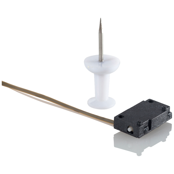
Image: Nanomotion Edge motor element showing the rectangular PZT stator, ceramic friction tip, and drive rod. Source: Nanomotion
How elliptical motion arises
Most standing-wave linear motors use a rectangular plate stator with two piezoelectric elements bonded to opposite faces. The drive electronics excite two vibration modes simultaneously: a longitudinal mode (which produces displacement along the stator's length) and a bending mode (which produces displacement perpendicular to the contact surface). When these two modes are excited at the same frequency with a 90-degree phase offset, the tip traces an ellipse. During the forward portion of the ellipse, the tip contacts the runner and pushes it. During the return portion, the tip lifts off (or at least reduces contact force) and retracts. The net effect is continuous unidirectional motion.
This requires careful stator design to ensure the longitudinal and bending modes have nearly identical resonant frequencies, a condition called modal degeneracy. Achieving this degeneracy within the manufacturing tolerance budget is one of the principal engineering challenges in standing-wave motor design.
Representative products and specifications
Nanomotion Edge and HR series. Nanomotion (now part of Celera Motion / Novanta) pioneered the multi-element standing-wave motor concept. The HR series uses multiple finger-like stator elements pressed against a ceramic strip. The Edge motor produces 0.5 to 3.5 N of force per element, with speeds up to 250 mm/s. Resolution with a suitable encoder reaches below 1 nm. Multiple elements can be ganged for higher force (the HR8, with eight fingers, produces up to 28 N). Operating frequency is around 39.6 kHz. These motors are widely used in semiconductor inspection, photonics alignment, and medical devices.
PI PILine series. Physik Instrumente's PILine motors use a rectangular piezoceramic plate bonded to a metal stator body. A single ceramic friction tip contacts an alumina drive rod. The U-264 OEM module produces approximately 2 N of force at speeds up to 400 mm/s (one of the fastest standing-wave designs available). Resolution depends on the encoder but reaches 50 nm routinely and below 5 nm with high-grade encoders. Travel is limited only by the drive rod length, with standard stages offering 13 to 305 mm. The N-664 NEXACT stage built on PILine technology achieves 0.03 nm resolution with a capacitive sensor.
New Scale Technologies SQUIGGLE. The SQUIGGLE motor is a distinctive variant: a hollow square tube of four piezoelectric plates bonded together. Exciting the plates in sequence creates a standing wave that orbits the tube, threading a central screw through the assembly. The result is a rotary-to-linear motor that fits in a 2.8 x 2.8 x 6 mm package. Force is 0.5 N, speed is 7 mm/s, and the stroke depends on the threaded rod length (up to 6 mm in standard configurations). The SQUIGGLE is used extensively in miniature camera autofocus, endoscope tip positioning, and portable medical devices where size is the overriding constraint.
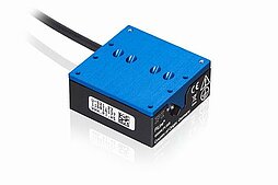
Image: PI U-521 PILine miniature linear stage, an integrated standing-wave ultrasonic motor system. Source: Physik Instrumente (PI)
Xeryon Crossfixx. Xeryon's patented cross-spring mechanism uses a standing-wave motor with integrated linear encoder, offered as a compact closed-loop stage. The XLS-Series provides up to 40 mm travel, 150 mm/s speed, 5 N force, and 50 nm bidirectional repeatability. Vacuum-compatible variants are available for semiconductor and space applications.
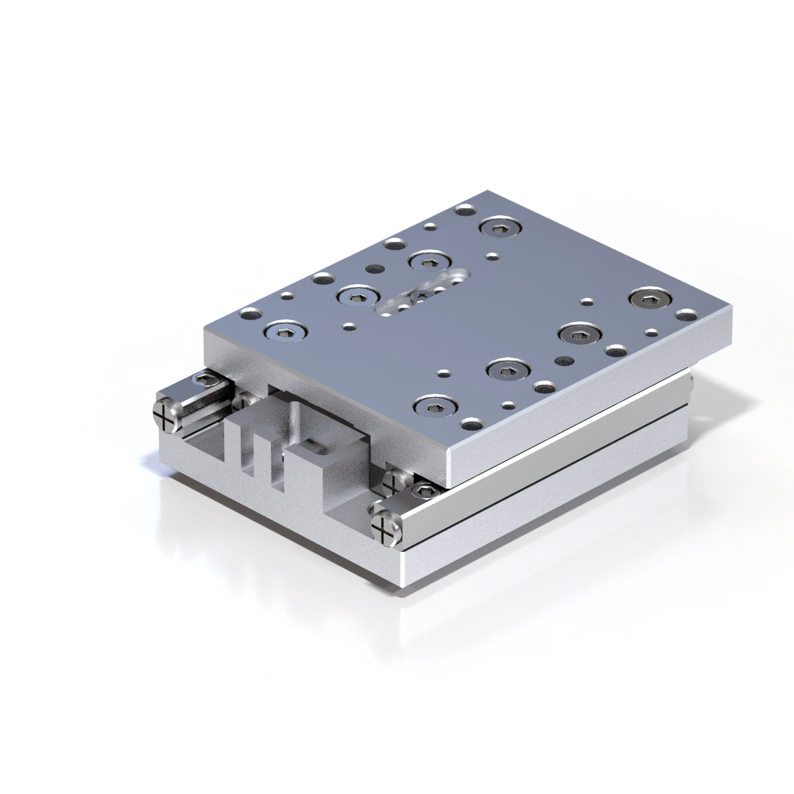
Image: Xeryon XLS ultrasonic linear stage with Crossfixx piezo motor. Source: Xeryon
Thorlabs Elliptec. Thorlabs licenses Elliptec resonant motor modules for slider and rotation stages. These are compact, low-cost modules operating near 100 kHz, with speeds up to 200 mm/s and forces around 1 N. They target beam steering, filter wheel rotation, and optical path switching in instruments.
Performance envelope
Standing-wave motors excel in the regime of moderate speed (1 to 400 mm/s), moderate force (0.5 to 30 N), and very high resolution (sub-nanometer with appropriate feedback). They self-lock when power is removed, drawing zero current at rest. Wear at the friction interface limits lifetime, typically to 5,000 to 20,000 hours of active motion or 10,000 to 100,000 km of cumulative travel (see life expectancy and wear). They generate negligible magnetic fields, making them suitable for electron-beam and MRI-adjacent applications.
Traveling wave motors
Traveling-wave motors create continuous rotary motion by generating a flexural wave that propagates around a ring-shaped stator. Unlike standing-wave motors, where the vibration pattern is stationary and the friction tip pushes in one direction, a traveling wave physically moves around the stator like a wave on water. Points on the stator surface trace elliptical paths, and a rotor pressed against the surface rides the wave.
Operating principle
A ring stator is excited by two sets of electrodes, spatially offset by a quarter wavelength, driven with sinusoidal signals 90 degrees out of phase. This creates two standing waves that combine into a single traveling wave. Each surface point traces a retrograde ellipse: when the wave crest passes, the surface moves backward (against the wave propagation direction), and the friction contact drives the rotor in that backward direction. The rotor therefore turns opposite to the wave's propagation direction.
The wave speed on the stator is determined by the stator material properties and geometry. The rotor speed is a fraction of the wave speed, reduced by slip at the contact interface. Typical slip ratios are 5% to 30%, depending on load and preload force.
Canon USM and its legacy
The most commercially successful traveling-wave motor is Canon's Ultrasonic Motor (USM), introduced in 1987 for camera autofocus lenses. The USM uses a ring stator with a B(0,9) bending mode operating near 30 to 45 kHz. It produces 0.3 to 1.5 Nm of torque at speeds up to 100 RPM, with startup from rest in under 50 ms. Nikon, Minolta (now Sony), and other camera manufacturers developed their own traveling-wave motors with similar specifications. Tens of millions of these motors have been manufactured.
The camera application favors traveling-wave motors because: the motion is smooth (no stepping or pulsing); the motor is silent at the ultrasonic operating frequency; the ring shape fits naturally around a cylindrical lens barrel; and the motor self-locks when unpowered, holding the lens position without battery drain.
Industrial variants
Outside consumer optics, traveling-wave motors are less common in precision positioning than standing-wave types. The principal industrial suppliers include:
Shinsei Corporation. Shinsei (Japan) produces the USR series of traveling-wave rotary motors in sizes from 30 to 100 mm diameter. The USR-60 (60 mm OD) produces 0.5 Nm peak torque at 100 RPM, with holding torque of 1.0 Nm. Operating frequency is around 40 kHz. These motors are used in robot joints, antenna positioners, and optical instrument turrets.
PI (Physik Instrumente). PI offers traveling-wave rotary stages in the U-6xx series for applications requiring smooth, backlash-free rotation with self-locking. Torques range from 0.1 to 0.8 Nm with speeds up to 120 RPM.
Niche vendors and custom designs. Several smaller manufacturers (PCBMotor in Denmark, Piezo Sonic in Japan) produce traveling-wave motors for specific applications, often customized for particular torque, speed, and form factor requirements.
Strengths and limitations
Traveling-wave motors offer smoother motion than standing-wave types because every point on the stator contributes to driving the rotor simultaneously, averaging out local contact irregularities. They are inherently rotary, which is an advantage for turret, dial, and gimbal applications but a disadvantage when linear motion is needed. Speed is moderate (up to 150 RPM for small motors) and torque is modest (0.1 to 2 Nm). Efficiency is relatively low, typically 25% to 50%, because energy is dissipated both in the stator's internal damping and at the contact interface.
The two-phase drive requirement adds electronic complexity compared to single-phase standing-wave motors, and the ring stator is more difficult and expensive to manufacture than a simple rectangular plate. For these reasons, traveling-wave motors are generally chosen only when their specific advantages (smooth rotary motion, self-locking, silence, ring form factor) outweigh the cost and complexity penalties.
Stick-slip (inertia) drives
Stick-slip motors, also called inertia drives, use an entirely different principle from resonant ultrasonic motors. Instead of continuous vibration at resonance, a stick-slip drive applies an asymmetric waveform (typically a sawtooth or modified sawtooth) to a piezoelectric actuator bonded to a platform or guide. During the slow ramp phase ("stick"), the actuator expands gradually, and friction between the moving platform and a sliding element causes both to move together. During the fast retract phase ("slip"), the actuator contracts rapidly, and the inertia of the sliding element keeps it in place while the actuator snaps back. The net result is a small step in one direction per cycle.
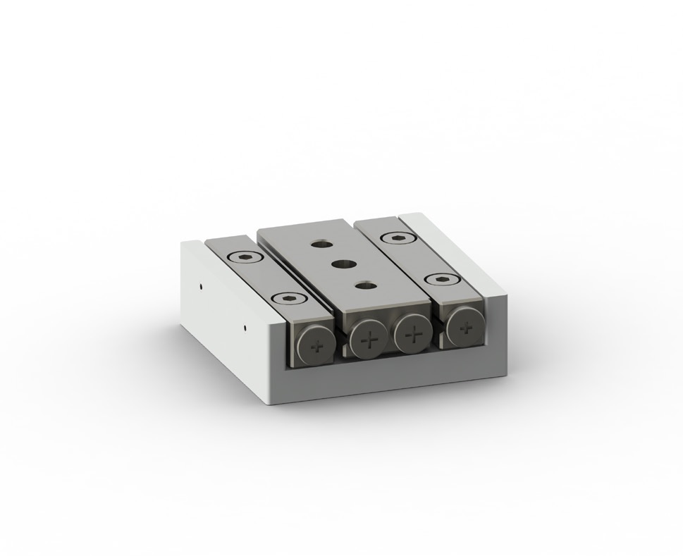
Image: SmarAct SLC-2430 stick-slip positioner, showing the compact form factor typical of inertia drive stages. Source: SmarAct
Physics of the step
The step size per cycle depends on the piezo actuator's stroke (typically 0.1 to 5 um), the waveform shape, the friction coefficient, the mass ratio between the moving parts, and the drive frequency. At drive frequencies of 10 to 20 kHz, a stick-slip motor produces thousands of steps per second, each a fraction of a micrometer. The cumulative effect is smooth macroscopic motion at speeds typically ranging from 0.5 to 20 mm/s.
The beauty of this approach is that travel is unlimited. The piezo actuator displaces only a few micrometers per cycle, but the stepping repeats indefinitely. Travel is limited only by the length of the guide rail, not by the actuator stroke. This distinguishes stick-slip motors from piezo stack actuators, which are limited to the stack's expansion range.
Resolution is determined by the minimum step size, which can be controlled by reducing the drive voltage. Commercial stick-slip positioners routinely achieve step sizes below 100 nm in open loop and below 1 nm with closed-loop encoder feedback.
Representative products
SmarAct SLC and SLC-24 series. SmarAct (Germany) is arguably the leading stick-slip positioner manufacturer. The SLC-1730 provides 21 mm travel, 1 nm resolution (closed-loop with an integrated nanometric sensor), 20 mm/s speed, and 1.5 N drive force. The compact form factor (17 x 17 x 7.5 mm for the actuator head) enables dense multi-axis assemblies. SmarAct's key differentiator is the integrated sensor: their SCL (SmarAct Closed Loop) technology uses a proprietary nanometric encoder directly in the positioner, eliminating external encoder mounting. The PICOSCALE interferometric sensor option achieves 1 pm resolution. Vacuum-compatible (10^-9 mbar) and cryogenic (4 K) variants are standard catalog items.
attocube ANPx, ANPz, ANR series. attocube systems (Germany, now part of Wittenstein) pioneered stick-slip positioners for extreme environments. The ANPx101 linear positioner offers 5 mm travel, 200 nm step size (open loop), up to 3 mm/s speed, and operates at temperatures from 10 mK to 300 K and in magnetic fields up to 31 T. Force is approximately 0.5 N. These units are the workhorse of low-temperature scanning probe microscopy and are installed in thousands of cryostats worldwide.
MKS/Newport Picomotor. The Picomotor is a long-established stick-slip product that uses a piezo element to rotate a fine-pitch screw against a sliding jaw. Step size is approximately 30 nm with forces up to 22 N (depending on the model). Speed is modest, around 1 to 3 mm/s. The Picomotor's strength is simplicity: no encoder is needed for many alignment applications because the steps are predictable enough for open-loop use. It is widely used in optics mount adjustment, mirror alignment, and laboratory fixtures.
Thorlabs PIA series and ORIC. Thorlabs offers the PIA13 and PIA25V inertia actuators with 6 mm and 16 mm travel, respectively. Step sizes range from 20 nm to 5 um depending on drive voltage. Speed reaches 5 mm/s. The ORIC (Optical Rail Inertia Carriage) integrates a PIA actuator on a dovetail rail for modular optical setups.
mechOnics MS and nanopositioner series. mechOnics (Germany) provides stick-slip nanopositioners for microscopy and nanofabrication. The MS30 offers 12 mm travel with step sizes down to 50 nm and integrated optical encoders for closed-loop operation.
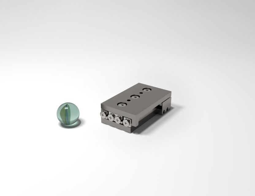
Image: SmarAct SLC-2445 positioner with a glass marble for scale, illustrating the miniature dimensions achievable with stick-slip technology. Source: SmarAct
Why stick-slip wins in extreme environments
The defining advantage of stick-slip drives is environmental versatility. Because the operating principle relies on inertia and friction rather than resonance or continuous vibration, stick-slip motors work at cryogenic temperatures (down to millikelvin), in ultra-high vacuum (10^-11 mbar), in high magnetic fields, and under radiation. The piezo actuator is a monolithic ceramic with no coils, no lubricants, and no organic materials (in the best designs). The friction interface is ceramic-on-ceramic or sapphire-on-sapphire.
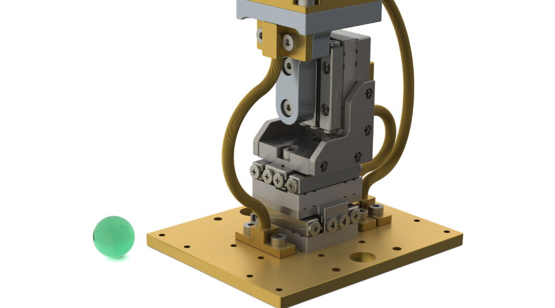
Image: SmarAct XYZ cryogenic positioner stack, designed for operation inside dilution refrigerators at temperatures down to 10 mK. Source: SmarAct
No other piezo motor technology matches this environmental range. Standing-wave motors rely on polymer-bonded assemblies and preload springs that may not survive cryogenic cycling. Traveling-wave motors use epoxy bonds and rely on consistent friction coefficients that change dramatically at low temperatures. Stick-slip positioners from attocube and SmarAct routinely operate inside dilution refrigerators at 10 mK, which is simply not possible with resonant ultrasonic motors.
The trade-off is performance: stick-slip motors are slower (typically 1 to 20 mm/s versus 50 to 400 mm/s for standing-wave) and produce less force (0.3 to 5 N versus 2 to 30 N for multi-element standing-wave motors). They also exhibit inherently stepped motion, which can introduce velocity ripple at low speeds unless smoothed by closed-loop control.
Walking (inchworm) motors
Walking motors, also called inchworm motors or clamp-step-release motors, coordinate multiple piezo actuators in a sequential gripping cycle that resembles bipedal walking. The principle: one set of actuators clamps the load, a second set extends to advance it, the first set releases, and the second set retracts to prepare for the next step. By overlapping the cycles of multiple actuator groups, the motor produces quasi-continuous motion with very high force and no sliding friction during the push phase.
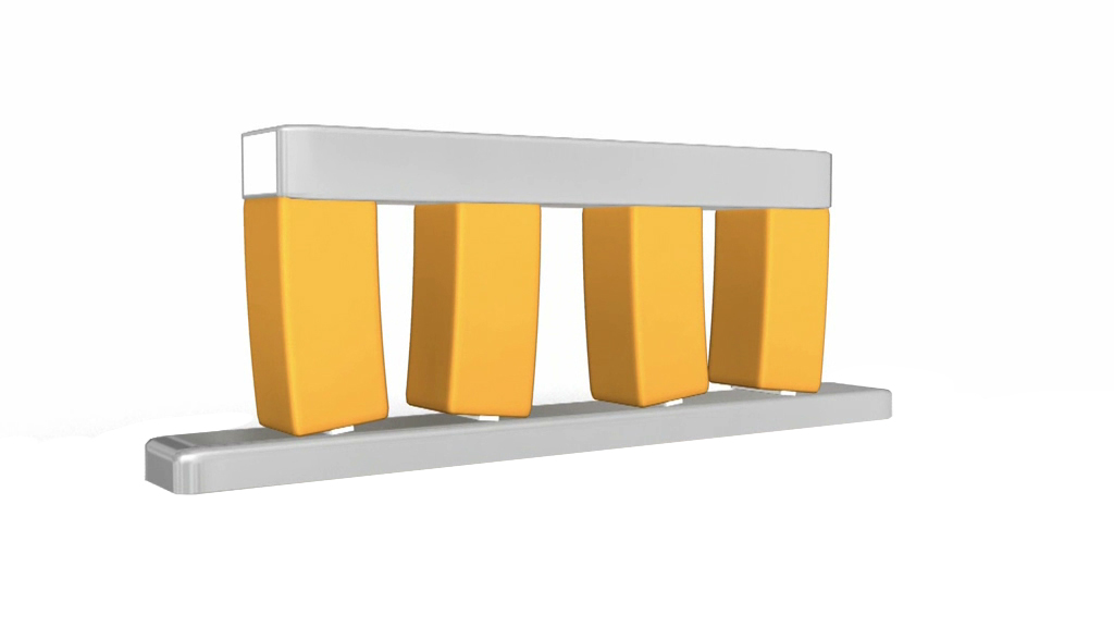
Image: PI NEXACT walking motor assembly showing the coordinated piezo actuator legs that clamp and push in sequence. Source: Physik Instrumente (PI)
Operating principle in detail
A typical walking motor has two or three sets of piezo actuators arranged in pairs. Each set includes clamping actuators (which grip the drive rod or rail by expanding laterally) and pushing actuators (which extend longitudinally to advance the clamped section). The cycle is:
- Group A clamps the rail.
- Group A's push actuators extend, advancing the rail by one step (typically 0.1 to 10 um).
- Group B clamps the rail.
- Group A releases.
- Group A's push actuators retract.
- Group A clamps again.
- Repeat.
With three groups operating 120 degrees out of phase, the motion is quasi-continuous. The rail experiences no net sliding friction because at least one group is always clamped and pushing; the rail never slides. This is fundamentally different from standing-wave and stick-slip motors, where friction sliding is the motion mechanism.
Representative products
PI NEXLINE series. PI's NEXLINE is the highest-force piezo motor commercially available. The N-216 NEXLINE actuator produces up to 600 N of pushing force at speeds up to 1 mm/s, with sub-nanometer resolution. Travel is unlimited (limited only by the guide rail or rod length). The NEXLINE uses a three-group walking mechanism with shear-mode piezo actuators for the clamping function and longitudinal-mode actuators for the pushing function. The N-216 is designed for applications requiring extreme force with nanometric precision: gravitational wave detector mirror positioning, large optic alignment in telescope instruments, and heavy-load nanopositioning in metrology.
PI NEXACT series. The NEXACT (N-664) is a compact walking motor that combines PILine resonant drive for fast coarse positioning with a PiezoWalk mechanism for fine nanopositioning in a single stage. The NEXACT achieves 0.03 nm resolution in the PiezoWalk mode, 200 mm/s in the PILine mode, and 10 N force. Travel ranges from 7.5 to 51 mm. This dual-mode architecture addresses the fundamental speed-versus-resolution trade-off: use the resonant mode to get close, then switch to the walking mode for final nanometric positioning.
PI PiezoWalk NEXLINE and N-331 series. The N-331 PiezoWalk uses four piezo actuator legs arranged in two pairs, walking a ceramic friction plate. It delivers up to 10 N force at 10 mm/s with 0.03 nm resolution. Travel is 10 to 20 mm. The design is optimized for nanopositioning stages in semiconductor metrology, scanning probe instruments, and interferometric alignment.
PiezoMotor LEGS (now Acuvi). The LEGS motor from PiezoMotor (Sweden, rebranded as Acuvi) uses a pair of bimorph bending actuators ("legs") that alternately grip and push a ceramic drive rod. Each leg bends in an arc, contacting the rod, pushing it forward, then lifting off as the other leg takes over. The LL06 LEGS motor produces 6 N force at up to 15 mm/s, with step sizes down to 0.5 nm. The form factor is compact (28 x 14 x 10 mm for the motor element), and the drive electronics are relatively simple compared to multi-group walking motors. LEGS motors are used in space instruments, portable spectrometers, and medical devices.
The force advantage
Walking motors produce the highest forces of any piezo motor technology. The 600 N of the NEXLINE dwarfs the 2 to 30 N of standing-wave motors and the 0.3 to 5 N of stick-slip drives. This force advantage comes from the clamping mechanism: the piezo actuators grip the rail with high normal force (generated by the d33 or d15 mode expansion of the clamping actuators), and the pushing force is limited by the clamping force times the friction coefficient, not by a vibrating tip's intermittent contact.
The trade-off is speed. Walking motors are slow. The stepping cycle takes time: each clamp-extend-release-retract sequence requires four to six electronic switching events per step, and the piezo actuators must fully extend and retract within each cycle. Typical speeds range from 0.01 to 15 mm/s. The PI NEXLINE maxes out at about 1 mm/s under load. For applications requiring nanometric positioning of heavy loads (optical tables, telescope mirrors, machine tool slides), this speed is adequate. For applications requiring rapid repositioning, it is not.
Sub-nanometer resolution
The resolution of walking motors is limited primarily by the strain resolution of the pushing actuators and the quality of the closed-loop feedback. Because each step is produced by a deterministic piezo expansion (not a stochastic friction event), the step size is highly controllable. With capacitive position sensors and closed-loop servo control, walking motors routinely achieve positioning resolution below 0.1 nm. This makes them the highest-resolution macroscopic positioning technology available, exceeding even flexure-guided piezo stack stages in some configurations.
Piezo stack actuators
Piezo stack actuators are the most fundamental piezo motion device: a pile of thin piezoelectric ceramic layers, poled in the thickness direction, with interleaved electrodes. Applying a voltage causes each layer to expand in the d33 mode (along the poling direction). The individual layer expansions accumulate, producing a total stroke proportional to the number of layers times the voltage times the d33 coefficient.
This is the simplest possible piezo motion technology. There is no friction interface, no resonance, no stepping mechanism. The ceramic deforms directly. The result is the fastest responding, highest-force, finest-resolution actuator in the piezo family, but with severely limited stroke.
Operating characteristics
The expansion of a piezo stack is approximately:
delta_L = n * d33 * V
where n is the number of layers, d33 is the piezoelectric charge coefficient (typically 300 to 600 pm/V for PZT-5H), and V is the applied voltage. For a 10 mm long stack with 100 layers of 100 um thickness, driven at 150 V, the stroke is roughly 100 * 500e-12 * 150 = 7.5 um. Practically, commercial stacks achieve 0.1% to 0.15% strain, so a 10 mm stack produces 10 to 15 um of stroke. A 100 mm stack produces 100 to 150 um.
The piezoelectric effect article covers the d33 coefficient and its material dependencies in depth.
Force capability
Piezo stacks generate enormous forces. The blocking force (maximum force at zero displacement) is:
F_block = k * delta_L_max
where k is the stack stiffness. A typical 10 x 10 x 18 mm stack has a stiffness of approximately 200 N/um and a free stroke of 15 um, giving a blocking force of 3,000 N. Larger stacks reach higher: the PI P-025 PICA stack (25 mm diameter, 36 mm long) produces up to 30 kN blocking force. The largest commercial stacks (PI P-056 series, 75 mm diameter) generate up to 70 kN.
These forces dwarf every other piezo technology. Walking motors reach 600 N; standing-wave motors reach 30 N. Only hydraulic and electromagnetic systems compete with piezo stacks on raw force output.
Response time
Because there is no mechanical drivetrain, no friction interface, and no resonance ring-up, piezo stack actuators respond on the microsecond timescale. The electrical time constant is RC (stack capacitance times driver output impedance), typically 1 to 100 us. The mechanical time constant is set by the stack's first resonant frequency, typically 10 to 100 kHz for stacks shorter than 50 mm. A 20 mm stack with a 50 kHz resonance can complete a full-stroke step in approximately 10 us.
This makes piezo stacks the fastest macro-scale actuator available. No electromagnetic actuator comes close to this response speed at comparable force levels.
Representative products
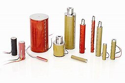
Image: PI PICA stack actuator collection showing the range of form factors, from small 5 mm chips to large 25 mm power actuators. Source: Physik Instrumente (PI)
PI PICA and PICMA series. PI produces the widest range of commercial piezo stacks. The P-885 PICMA (multilayer, 5 x 5 x 9 mm) delivers 9.1 um stroke, 1,750 N blocking force, and has a resonant frequency of 142 kHz. The P-025 PICA Power Actuator (25 mm diameter, 36 mm long) delivers 38 um stroke with 30 kN blocking force. Operating voltage is 0 to 120 V for multilayer types and 0 to 1,000 V for high-voltage types. Lifetime at reduced voltage and stroke exceeds 10^10 cycles (tens of billions), far surpassing any friction-based motor.
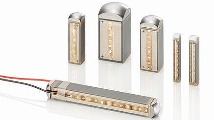
Image: PI PICMA multilayer stack actuators in several sizes, with visible ceramic layer construction. Source: Physik Instrumente (PI)
Noliac (CTS) NAC series. Noliac (now part of CTS Corporation) supplies OEM piezo stacks in standard sizes from 2 x 2 x 2 mm to 10 x 10 x 56 mm. The NAC2015-H12 produces 12 um stroke at 200 V with 4,600 N blocking force. These are widely used as the force-generating element inside flexure nanopositioning stages.
Thorlabs PK and PA series. Thorlabs offers multilayer piezo stacks for optical and photonic applications. The PK4CMP2 (5 x 5 x 10 mm) provides 11.2 um stroke at 150 V. The PA4HKW is a high-voltage stack producing 19.8 um at 1,000 V.
TDK and Tokin. Japanese manufacturers supply large volumes of multilayer piezo stacks for automotive (fuel injectors, where billions of units have been deployed) and industrial applications.
Where stacks fit in the motion landscape
Piezo stacks are not motors. They do not produce unlimited travel. Their stroke is inherently limited to 0.1% to 0.15% of their length. A 10 mm stack gives 10 to 15 um. A 100 mm stack gives 100 to 150 um. For applications requiring more than about 200 um of travel, stacks must be combined with mechanical amplification (next section), used as the drive element inside a motor mechanism (walking motors, stick-slip drives), or paired with a flexure stage to convert small displacement into useful positioning.
The vast majority of piezo stacks are deployed inside flexure-guided nanopositioning stages, where they provide the force and displacement that the flexure mechanism guides and the closed-loop control system refines. PI's P-6xx NanoPositioning stages, nPoint's NPXY series, and Mad City Labs' Nano-PDQ series all use piezo stacks as the internal actuator. These stages deliver 1 to 300 um of travel with sub-nanometer resolution and bandwidths of 1 to 10 kHz, serving as the backbone of scanning probe microscopy, semiconductor lithography, and precision optics alignment.
Amplified piezo actuators
Amplified piezo actuators address the fundamental limitation of piezo stacks (tiny stroke) by using a mechanical amplification structure to multiply the stack's displacement by a factor of 5 to 20x. The result is a self-contained actuator with strokes of 0.1 to 2 mm, retaining much of the stack's force and speed, though both are reduced by the amplification ratio.
The Cedrat APA
Cedrat Technologies (France) defined this product category with the Amplified Piezo Actuator (APA). The APA consists of a piezo stack housed inside an elliptical metal shell. When the stack expands, the shell's minor axis elongates; conservation of volume causes the major axis to contract. The net effect is that the output (at the shell's ends along the major axis) moves with amplified displacement relative to the stack expansion.
The amplification factor depends on the shell's geometry: thinner, more eccentric ellipses amplify more but reduce stiffness and force proportionally. Typical factors are 5x to 20x.
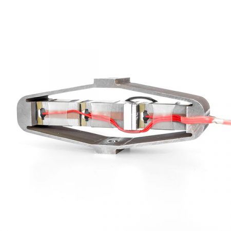
Image: Cedrat APA300ML amplified piezo actuator with the characteristic elliptical shell that amplifies the internal stack displacement. Source: Cedrat Technologies
Cedrat APA120ML. Stack voltage: 0 to 150 V. Free stroke: 126 um (amplified from approximately 15 um of stack expansion, roughly 8x amplification). Blocking force: 38 N. Stiffness: 0.3 N/um. Resonant frequency: 1,460 Hz. This is the compact workhorse for vibration control, active optics, and adaptive structures.
Cedrat APA400M. Free stroke: 400 um. Blocking force: 92 N. Resonant frequency: 710 Hz. Used in space mechanisms, active damping systems, and precision tool actuation.
Cedrat APA1000XL. Free stroke: 1,010 um (over 1 mm). Blocking force: 36 N. Resonant frequency: 230 Hz. Approaches the stroke regime of small linear motors while retaining the deterministic response characteristics of a piezo actuator.
Built-in preload
A critical feature of the elliptical shell design is that it preloads the piezo stack in compression. PZT ceramics are strong in compression (withstanding 100+ MPa) but weak in tension (failing at 5 to 10 MPa). In a raw stack, rapid deceleration or external tensile loads can crack the ceramic. The APA's shell always keeps the stack in compression, even when the output is pulled in the extending direction. This makes the APA more mechanically robust than a bare stack for dynamic applications.
Application domains
Amplified piezo actuators fill a niche between stack actuators (high force, tiny stroke) and motor-driven stages (unlimited travel, lower resolution). They are used in:
- Active vibration control. Mounted in structural paths to cancel vibration. The 1 to 2 kHz resonant frequency matches the control bandwidth needed for isolation of sensitive instruments.
- Space mechanisms. Cedrat APAs have flown on multiple ESA and CNES missions. The solid-state construction, with no lubricants or bearings, suits the vacuum and thermal cycling of space.
- Adaptive optics. Deformable mirror actuators requiring 10 to 100 um stroke with sub-micrometer precision.
- Valve actuation. Proportional valve control in pneumatic and hydraulic systems requiring fast response (milliseconds) with moderate stroke.
- Ultrasonic tool actuation. High-frequency vibration superimposed on a machining tool for ultrasonic-assisted cutting.
Other manufacturers of amplified piezo actuators include Noliac/CTS (which produces amplified actuators under its own brand), Thorlabs (with the AE series of amplified actuators), and Dynamic Structures & Materials (DSM) in the United States, which produces custom amplified actuators for aerospace applications.
Shear, bending, and tube actuators
Several piezo actuator technologies operate as component-level devices, typically embedded within larger positioning systems rather than sold as complete motor assemblies. These are the workhorses of scanning probe microscopy, micro-optic alignment, and precision instrument design.
Shear-mode actuators (d15)
A piezo ceramic operated in shear mode produces lateral displacement when an electric field is applied perpendicular to the poling direction. The d15 coefficient is typically 2 to 3 times larger than d33 in soft PZT materials (d15 approximately 700 to 800 pm/V for PZT-5H versus d33 approximately 500 to 600 pm/V), making shear mode attractive for maximizing displacement from a given voltage.
Shear actuators produce in-plane motion without the tilting artifacts that plague d31-mode benders. A single shear plate driven at 200 V can produce 1 to 5 um of lateral displacement. They are used inside walking motors (PI NEXLINE uses shear-mode actuators for the clamping function), in nanopositioner stages, and in micro-optic alignment devices.
Commercially, PI produces shear plates (P-141 to P-143 series) with strokes up to 10 um at 250 V. Noliac supplies custom shear elements for OEM integration. The primary limitation is the relatively low force output (10 to 100 N) compared to d33 stack actuators and the difficulty of achieving large strokes without stacking multiple shear plates.
Bimorph benders
A bimorph bender consists of two piezo layers bonded together with opposite poling directions (or one piezo layer bonded to a passive metal shim). When voltage is applied, one layer expands while the other contracts (or stays fixed), causing the assembly to bend. This converts the small in-plane strain of the ceramic into a much larger tip deflection, at the cost of reduced force.
A typical bimorph bender 30 mm long and 1 mm thick produces 0.5 to 1 mm of tip deflection at 200 V, with a force of 0.1 to 0.5 N. The deflection-to-length ratio is much larger than a stack actuator's strain, making benders useful for applications requiring moderate displacement in a compact form.
Applications include textile valves (fast switching with small force), Braille displays (arrays of bimorph actuators raising and lowering dots), micro-mirror tilt actuators, and energy harvesting from ambient vibrations. In the motion technology context, benders are used as the drive element in some compact piezo motor designs; the PiezoMotor LEGS motor, for example, uses bimorph bending actuators as its "walking legs."
Tube scanners
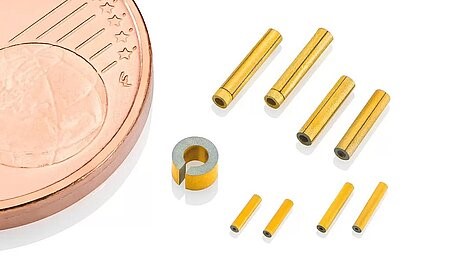
Image: PZT piezo scanner tubes in various sizes, shown next to a euro coin for scale. These hollow ceramic cylinders provide three-axis scanning motion for SPM. Source: Physik Instrumente (PI)
Piezo tube scanners are hollow, thin-walled PZT cylinders with four external electrodes (quadrants) and a single internal electrode. Applying differential voltages to opposite quadrant pairs causes the tube to bend in X and Y, while a common-mode voltage to all four quadrants produces Z displacement (extension or contraction). A single tube thus provides three-axis scanning motion in a minimal package.
Tube scanners are the standard actuator in scanning tunneling microscopes (STM) and atomic force microscopes (AFM). A typical tube scanner (12.7 mm OD, 50 mm long, 0.5 mm wall thickness) provides 50 to 100 um of XY scan range and 5 to 10 um of Z range at 200 V. Resolution is sub-angstrom, as demonstrated by the atomic-resolution imaging routinely achieved in SPM.
The limitations of tube scanners are well known: significant cross-coupling between X, Y, and Z axes; hysteresis of 10% to 15% (common to all piezo actuators operated open-loop); creep of 1% to 10% over minutes; and limited scan speed due to the tube's low resonant frequency (typically 1 to 10 kHz). For high-speed or large-range scanning, flexure stages with stack actuators have largely supplanted tube scanners in research instruments, though tubes remain dominant in commercial SPM due to their simplicity and low cost.
Cross-technology comparison
With all the major piezo motion technologies described, we can now compare them quantitatively. The following analysis covers the key performance parameters that determine technology selection.
Speed
Standing-wave ultrasonic motors lead in speed among friction-driven piezo motors, with the fastest designs (PI PILine U-264) reaching 400 mm/s. Traveling-wave rotary motors achieve 100 to 150 RPM, corresponding to 30 to 50 mm/s of tangential speed at the contact surface for a 60 mm diameter motor. Stick-slip drives are slower, typically 1 to 20 mm/s, with the best designs (SmarAct SLC-17 series) reaching 20 mm/s. Walking motors are the slowest friction-based technology, maxing out at 1 to 15 mm/s. Piezo stack actuators do not produce continuous speed; they execute single strokes in microseconds, corresponding to transient velocities that can exceed 1 m/s but only over micrometer-scale distances.
Force
Piezo stacks dominate force output, reaching 70 kN for large stacks. Walking motors are next, with the PI NEXLINE producing 600 N. Standing-wave motors produce 0.5 to 30 N depending on configuration (single element to ganged HR8). Traveling-wave motors generate 0.1 to 2 Nm of torque. Stick-slip drives produce 0.3 to 5 N, with the MKS Picomotor reaching 22 N through its screw mechanism.
Resolution
Walking motors achieve the finest resolution among motor technologies: below 0.03 nm with capacitive feedback (PI NEXACT). Standing-wave motors reach below 1 nm with appropriate encoders. Stick-slip drives achieve 1 nm or better closed-loop (SmarAct with SCL sensor). Piezo stacks in flexure stages achieve sub-angstrom resolution in principle, limited by electronics noise and sensor noise rather than the actuator itself. Traveling-wave motors have the coarsest resolution of the group, typically 0.5 to 5 um, limited by the contact dynamics and the difficulty of implementing high-resolution encoders in a rotary configuration.
Stroke and travel
Stick-slip and standing-wave motors offer unlimited travel (limited only by guide rail length), with commercial stages available up to 300+ mm. Traveling-wave motors provide unlimited rotary travel. Walking motors also offer unlimited travel. Piezo stacks are limited to 5 to 200 um. Amplified piezo actuators extend this to 0.1 to 2 mm. Tube scanners provide 50 to 100 um of XY range.
Self-locking
All friction-based piezo motors (standing-wave, traveling-wave, stick-slip, walking) self-lock when power is removed. The friction preload holds the load in position with zero current draw. Piezo stacks do not self-lock; they return to their unpowered length when voltage is removed (though hysteresis causes the return position to differ slightly from the starting position). Amplified actuators inherit this non-locking behavior.
Wear and lifetime
Piezo stacks have the longest lifetime: 10^10+ cycles at derated voltage, effectively unlimited for most applications. Walking motors have low wear because there is no sliding friction during the push phase; the clamping actuators grip and release without relative motion. Lifetime data is limited, but PI reports millions of cycles without measurable degradation. Standing-wave motors wear at the friction interface, with typical lifetimes of 5,000 to 20,000 hours of active motion. Traveling-wave motors have similar wear characteristics. Stick-slip motors wear at the friction interface, with lifetimes comparable to standing-wave types for equivalent duty cycles.
Environment compatibility
Stick-slip drives offer the widest environmental operating range: cryogenic (10 mK to 300 K), UHV (10^-11 mbar), high magnetic fields (31 T+), and radiation environments. Standing-wave motors operate in vacuum (10^-6 to 10^-8 mbar with appropriate materials) and moderate temperature ranges (-20 to 80 C typical). Walking motors have good vacuum compatibility (PI NEXLINE and NEXACT are available in vacuum variants to 10^-6 mbar) and operate at temperatures from -40 to 80 C. Traveling-wave motors are the most environmentally limited, with standard operation at ambient conditions only; vacuum and cryogenic variants are rare. Piezo stacks themselves are vacuum and temperature compatible, limited mainly by the wire insulation and adhesive bond layers (typically -40 to 150 C).
Complexity and cost
Stick-slip drives are the simplest to implement: a single piezo actuator, a sawtooth waveform generator, and a friction guide. Driver electronics can be as simple as a signal generator and amplifier. The MKS Picomotor driver is a standalone box that costs approximately $1,500 per channel. Complete SmarAct positioners cost $2,000 to $5,000 per axis, depending on sensor options.
Standing-wave motors require precision drive electronics with frequency tracking (PLL or admittance control) and typically need closed-loop encoder feedback for positioning. Complete PILine stages cost $3,000 to $8,000 per axis. Nanomotion Edge modules cost $500 to $1,500 per motor element, plus driver and stage.
Walking motors have the most complex drive electronics (multi-phase waveform generation with precise timing) and require high-resolution encoders. Complete PI NEXLINE stages cost $5,000 to $15,000 per axis. The NEXACT dual-mode stages cost $8,000 to $12,000.
Traveling-wave motors require two-phase drive electronics with frequency tracking. Shinsei motors cost $200 to $800 per motor, plus driver. Complete rotary stages cost $2,000 to $5,000.
Piezo stacks are inexpensive ($20 to $500 for the ceramic) but require a high-voltage amplifier ($500 to $3,000) and, for precision use, a flexure stage ($2,000 to $15,000) and capacitive position sensor ($2,000 to $5,000).
Cross-Technology Comparison
| Parameter | Standing wave | Traveling wave | Stick-slip | Walking | Piezo stack | Amplified |
|---|---|---|---|---|---|---|
| Max Speed | 400 mm/s | 50 mm/s | 20 mm/s | 15 mm/s | N/A | N/A |
| Max Force | 30 N | 2 Nm | 22 N | 600 N | 70 kN | 200 N |
| Resolution | < 1 nm | 0.5 um | < 1 nm | 0.03 nm | < 0.1 nm | 1 nm |
| Travel | Unlimited | Unlimited | Unlimited | Unlimited | 5-200 um | 50-2000 um |
| Self-locking | Yes | Yes | Yes | Yes | No | No |
| Vacuum | HV | Ambient | UHV | HV | UHV | HV |
| Cryogenic | No | No | 10 mK | -40 C | -40 C | -40 C |
| Electronics | Moderate | Complex | Simple | Complex | Simple | Simple |
| Cost / axis | $3-8k | $2-5k | $2-5k | $5-15k | $5-20k | $0.5-3k |
Comprehensive comparison table
| Parameter | Standing wave | Traveling wave | Stick-slip | Walking | Piezo stack | Amplified piezo |
|---|---|---|---|---|---|---|
| Speed | 1 to 400 mm/s | 30 to 50 mm/s (tangential) | 0.5 to 20 mm/s | 0.01 to 15 mm/s | N/A (single stroke) | N/A (single stroke) |
| Force | 0.5 to 30 N | 0.1 to 2 Nm torque | 0.3 to 22 N | 10 to 600 N | 1,000 to 70,000 N | 10 to 200 N |
| Resolution (closed-loop) | < 1 nm | 0.5 to 5 um | < 1 nm | < 0.03 nm | < 0.1 nm | 1 to 50 nm |
| Stroke / travel | Unlimited (rail length) | Unlimited (rotary) | Unlimited (rail length) | Unlimited (rail length) | 5 to 200 um | 50 to 2,000 um |
| Self-locking | Yes | Yes | Yes | Yes | No | No |
| Typical lifetime | 5,000 to 20,000 hrs | 5,000 to 15,000 hrs | 5,000 to 20,000 hrs | > 10,000 hrs (est.) | > 10^10 cycles | > 10^9 cycles |
| Vacuum (mbar) | 10^-6 to 10^-8 | Ambient only (typical) | 10^-9 to 10^-11 | 10^-6 | 10^-9 | 10^-6 to 10^-8 |
| Temp range | -20 to 80 C | 5 to 50 C (typical) | 0.01 to 300 K | -40 to 80 C | -40 to 150 C | -40 to 80 C |
| Magnetic sensitivity | None | None | None | None | None | None |
| Drive electronics | PLL/admittance tracking | Two-phase + PLL | Sawtooth generator | Multi-phase timing | High-voltage amplifier | High-voltage amplifier |
| Driver complexity | Moderate | Moderate to high | Low | High | Low (analog) | Low (analog) |
| Typical stage cost | $3,000 to $8,000 | $2,000 to $5,000 | $2,000 to $5,000 | $5,000 to $15,000 | $5,000 to $20,000 (with stage) | $500 to $3,000 |
| Motion type | Linear (primarily) | Rotary (primarily) | Linear, rotary | Linear | Linear | Linear |
Choosing the right technology
The comparison table above contains dozens of data points, but technology selection for a specific application usually comes down to three or four parameters that dominate the decision. The following framework walks through the selection process.
Start with speed and stroke
If you need more than 50 mm/s sustained speed AND more than 10 mm of travel, the candidates are standing-wave ultrasonic motors and traveling-wave motors (for rotary). Stick-slip and walking motors are too slow for this regime.
If you need less than 1 mm/s AND less than 200 um of travel, a piezo stack actuator in a flexure stage is likely the best choice. The direct strain of the ceramic provides the highest resolution, fastest response, and longest lifetime.
If you need less than 20 mm/s with travel greater than 5 mm, all four motor types (standing-wave, stick-slip, walking, traveling-wave for rotary) are candidates, and the selection moves to force, resolution, and environment.
Then filter by force
If the application requires more than 50 N of continuous force, only walking motors (NEXLINE class) and piezo stacks (as actuators, not motors) remain. No other piezo technology delivers this force level.
If force requirements are below 5 N, all motor types are viable, and force is not a discriminating criterion.
Then filter by resolution
If the application requires resolution below 5 nm, walking motors and piezo stack stages are the natural choices. Standing-wave motors can reach this regime with premium encoders, but they were not designed for it. Stick-slip drives can achieve it with integrated nanometric sensors (SmarAct SCL).
If resolution below 0.1 nm is required, the candidates narrow to walking motors (NEXACT, NEXLINE in fine mode) and piezo stack flexure stages with capacitive sensors. Nothing else commercially available delivers this.
If resolution requirements are moderate (100 nm to 5 um), all technologies qualify, and the selection moves to environment and cost.
Then filter by environment
This is often the decisive criterion. If the application requires cryogenic operation (below -40 C), only stick-slip drives are practical. If UHV (below 10^-8 mbar) is needed, stick-slip drives are the first choice, followed by piezo stacks. If the application requires operation in high magnetic fields, only piezo-based technologies qualify (all types), eliminating any hybrid designs that incorporate electromagnetic components.
For standard laboratory or industrial conditions (ambient temperature, atmospheric pressure or moderate vacuum), environment is not a discriminating factor.
Finally, consider cost and complexity
For budget-constrained projects, stick-slip drives (MKS Picomotor, Thorlabs PIA) offer the lowest entry point at $500 to $2,000 per axis, including the driver. Standing-wave motors in integrated stages (Xeryon, Thorlabs Elliptec) are competitive at $2,000 to $4,000. Walking motors carry a premium ($5,000 to $15,000) that is justified only when their force or resolution advantages are required.
When each technology wins
Standing-wave ultrasonic motors win when the application needs moderate speed (10 to 400 mm/s), moderate force (1 to 10 N), compact size, self-locking, and encoder-level resolution (1 to 100 nm). This is the sweet spot for semiconductor inspection stages, photonics alignment, and medical device positioning. Products: PI PILine, Nanomotion Edge, Xeryon XLS.
Traveling-wave motors win when smooth, silent, self-locking rotary motion is needed in a compact ring form factor. Camera autofocus, turret rotation, and gimbal pointing are the core applications. They are rarely the best choice for precision linear positioning. Products: Shinsei USR, Canon USM.
Stick-slip (inertia) drives win when the application requires operation in extreme environments (cryogenic, UHV, high magnetic field) or when simplicity, compactness, and cost are paramount. They are the only practical technology for positioning inside dilution refrigerators, cryogenic STMs, and superconducting magnet bores. Products: SmarAct SLC, attocube ANP, MKS Picomotor.
Walking motors win when the application demands the combination of extreme force (10 to 600 N), sub-nanometer resolution, and long travel. Gravitational wave detector optics, telescope mirror alignment, heavy-load metrology stages, and nanolithography platforms are the applications that justify the cost and complexity. Products: PI NEXLINE, PI NEXACT, Acuvi LEGS.
Piezo stack actuators win when the application requires the absolute fastest response (microseconds), highest force (kN range), and highest resolution (sub-angstrom), within a stroke budget of less than 200 um. They are the engine inside virtually every nanopositioning stage and the actuator of choice for fast scanning, active vibration control, and deformable optics. Products: PI PICMA/PICA, Noliac NAC, Thorlabs PK.
Amplified piezo actuators win when strokes of 0.1 to 2 mm are needed with deterministic, hysteresis-compensable response and no friction wear, in applications where motor-based travel is not required. Space mechanisms, active damping, proportional valve control, and adaptive optics are the primary domains. Products: Cedrat APA, Thorlabs AE.
A note on hybrid approaches
The most capable precision positioning systems often combine technologies. A coarse/fine architecture might use a standing-wave motor for rapid coarse approach (100 mm of travel at 200 mm/s) and a piezo stack stage for fine positioning (50 um of range at sub-nanometer resolution). The PI NEXACT explicitly implements this, combining a PILine resonant motor and a PiezoWalk mechanism in a single stage. SmarAct's SLC positioners can be combined with piezo scanner stages for SPM applications.
The selection framework above identifies the primary positioning technology, but the system architect should always consider whether a secondary technology can address a requirement that the primary technology cannot meet. In many high-performance systems, the answer is yes.
Selecting the right piezo motion technology is fundamentally about matching physics to requirements. Each technology exploits a different physical mechanism, and each mechanism has inherent strengths and limitations that no amount of engineering can overcome. The framework above identifies which physics match which requirements. Define your requirements precisely, apply the filters in order, and the technology choice will emerge clearly. Where the choice is ambiguous, the comparison table provides the quantitative data to resolve the tie.