Technology
Piezo vs. stepper: resolution, noise, and why steps are the enemy of precision
Vibration, microstepping myths, resonance traps, and the quantitative case for piezo in precision positioning
Piezo vs. Stepper: Resolution, Noise, and Why Steps Are the Enemy of Precision
Stepper motors are the workhorse of affordable motion control. They are cheap, available from dozens of vendors in standardized NEMA frame sizes, and trivially simple to drive: pulse a pin, the shaft rotates 1.8 degrees. No encoder needed. No tuning. A NEMA 17 stepper costs five to fifty dollars, and a complete axis with driver, lead screw, and linear rail can be assembled for under two hundred. For 3D printers, CNC routers, laser cutters, and most industrial automation, the stepper motor is the obvious and correct choice.
But "cheap and easy" carries a physics tax. The very mechanism that makes stepper motors simple (discrete angular steps driven by electromagnetic detent torque) introduces vibration, resonance, and hard resolution limits that are structural, not incidental. These limitations are tolerable in general automation. In precision positioning, they become disqualifying.
This article examines the stepper motor's limitations against ultrasonic piezoelectric motor technology, using specific numbers from real products, measured data from independent testing, and worked engineering examples. The goal is not to argue that piezo motors are universally better. They are not. The goal is to map, with quantitative precision, the boundary where one technology should replace the other.
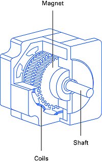 Hybrid stepper motor cutaway. The toothed rotor and electromagnetic detent mechanism produce the discrete steps, resonance, and vibration that limit precision positioning. Source: PI
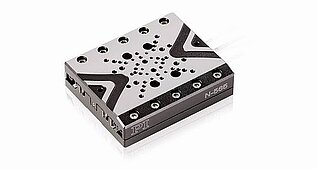
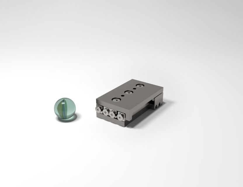 SmarAct SLC-2445 miniature piezo stage next to a marble for scale. At 13 g, this stage delivers sub-nanometer resolution and zero-power holding in a package roughly 1/40th the mass of a comparable stepper assembly. Source: SmarAct
| Parameter | Piezoelectric | Stepper |
|---|---|---|
| Resolution | 0.5 nm | 1-5 um |
| Speed | up to 800 mm/s | up to 1000 mm/s |
| Force | 0.5-20 N | 1-100 N |
| Holding Force | Unlimited | High with power |
| Vacuum Compatibility | Excellent | Poor (lubricant) |
| EMI | None | Moderate |
| Lifetime | 5000+ km | 10000+ hrs |
| Cost | High | Low |
Fundamental Operating Principles
How Stepper Motors Work
A hybrid stepper motor combines a permanent magnet rotor with toothed iron pole pieces and wound stator coils. The standard configuration has 50 rotor teeth and 2 phases, producing 200 full steps per revolution (1.8 degrees per step). When the controller energizes the next phase winding, the electromagnetic torque pulls the rotor forward by one tooth pitch, and the permanent magnet's detent torque locks it in place at the new position.
This is open-loop positioning. The controller counts pulses and assumes the rotor follows. No feedback sensor is required for basic operation, which is the stepper's primary advantage: simplicity.
Key electrical and mechanical parameters for common sizes:
| Parameter | NEMA 17 | NEMA 23 | NEMA 34 |
|---|---|---|---|
| Step angle | 1.8 deg (200 steps/rev) | 1.8 deg (200 steps/rev) | 1.8 deg (200 steps/rev) |
| Holding torque | 40 to 65 Ncm | 100 to 300 Ncm | 200 to 800 Ncm |
| Rated current per phase | 1.5 to 2.0 A | 2.0 to 4.2 A | 3.0 to 6.0 A |
| Phase resistance | 1.0 to 2.5 ohm | 0.5 to 1.8 ohm | 0.3 to 1.2 ohm |
| Rotor inertia | 35 to 70 gcm² | 154 to 840 gcm² | 500 to 4,000 gcm² |
| Step accuracy | +/- 3 to 5 arc-min (non-cumulative) | +/- 3 to 5 arc-min | +/- 3 to 5 arc-min |
The +/- 3 arc-minute accuracy specification (published by Oriental Motor and consistent across manufacturers) means that each individual step can deviate from its ideal 1.8-degree position by up to 0.05 degrees. This is a mechanical and magnetic property of the motor's construction; it cannot be improved by the driver electronics.
How Ultrasonic Piezo Motors Work
Ultrasonic piezo motors convert high-frequency vibration (typically 20 to 200 kHz) of a piezoelectric ceramic element into continuous linear or rotary motion through friction coupling at a contact interface. The ceramic vibrates at ultrasonic resonance, and the contact tip traces an elliptical path that pushes the moving platform forward in tiny increments, thousands to millions of times per second.
The result is continuous, not discrete motion. There are no steps, no detent torque, and no angular indexing. Speed is controlled by vibration amplitude. Position is held passively by friction preload, requiring zero electrical power at rest. The critical point for this comparison: there is no inherent discretization. A piezo motor can move by any arbitrary increment, limited only by encoder resolution and controller noise.
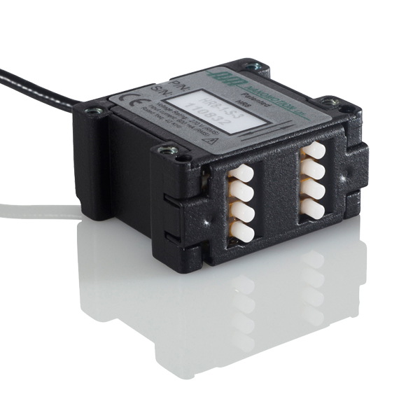 Nanomotion HR8 ultrasonic motor element. The ceramic tip vibrates at ultrasonic frequency, producing continuous motion with no discrete steps. Multiple HR elements can be combined for higher force output. Source: Nanomotion
The Microstepping Myth
This is the most important section in this article because it addresses the most common misconception in stepper motor specifications: the belief that microstepping provides proportional improvement in positioning resolution.
What Microstepping Actually Does
Microstepping divides each full step into smaller increments by applying sinusoidally varying currents to both phases simultaneously. Instead of full current on one phase and zero on the other (full-step mode), the controller creates intermediate current ratios that position the rotor between full-step detent positions.
Common microstep divisions are 1/2, 1/4, 1/8, 1/16, 1/32, 1/64, 1/128, and 1/256. With 1/256 microstepping on a 200-step motor, the theoretical resolution becomes 1.8 / 256 = 0.00703 degrees per microstep, or (with a 2 mm pitch lead screw) 0.039 micrometers per microstep.
This theoretical number is the one printed on data sheets. It is also, above about 1/16 microstepping, largely fictional.
The Torque Problem
Each microstep is held in position by the torque difference between adjacent microstep positions. As the microstep ratio increases, this incremental torque drops rapidly. At full step, the holding torque is 100% of the motor's rated torque. At 1/2 step, each microstep is held by approximately 70.7% of full torque (sin 45 degrees). At 1/4 step, 38.3%. The relationship follows a sine function, and at high divisions the numbers become vanishingly small.
At 1/256 microstepping, the torque available to hold the rotor at each microstep position is:
sin(180 / 256) = sin(0.703 degrees) = 0.0123, or 1.23% of full-step holding torque
For a NEMA 17 motor with 50 Ncm holding torque, each microstep at 1/256 is held by just 0.61 Ncm. Compare this with the motor's own detent torque (typically 3 to 8 Ncm for NEMA 17, or 6% to 16% of holding torque), the bearing friction (1 to 3 Ncm), and any lead screw friction. The microstep holding torque at 1/256 is smaller than the disturbance torques, which means the rotor cannot actually resolve those positions.
The Holding Torque Collapse Table
| Microstep Division | Torque per Microstep (% of full-step) | Torque per Microstep, NEMA 17 50 Ncm (Ncm) | Exceeds Detent Torque? | Exceeds Bearing Friction? |
|---|---|---|---|---|
| Full step (1/1) | 100% | 50.0 | Yes | Yes |
| 1/2 | 70.7% | 35.4 | Yes | Yes |
| 1/4 | 38.3% | 19.1 | Yes | Yes |
| 1/8 | 19.5% | 9.8 | Yes | Yes |
| 1/16 | 9.8% | 4.9 | Marginal (3 to 8 Ncm detent) | Yes |
| 1/32 | 4.9% | 2.5 | No | Marginal (1 to 3 Ncm) |
| 1/64 | 2.5% | 1.2 | No | No |
| 1/128 | 1.2% | 0.61 | No | No |
| 1/256 | 0.61% | 0.31 | No | No |
Beyond 1/16, the torque per microstep drops below the motor's own detent torque. Beyond 1/32, it drops below bearing friction. The rotor physically cannot resolve these fine microstep positions; it is fighting against forces larger than what the microstep current profile can produce.
Measured Data: The Evidence
Independent testing confirms the theory. Measurements reported in the Hackaday community (widely referenced in the stepper motor engineering literature) tested three popular stepper driver ICs with the same NEMA 17 motor (1.8 degree, 200 steps/rev):
Allegro A4988 (up to 1/16 microstepping): Position error at 1/16 was approximately 30% to 50% of a microstep size. Smooth motion improvement was evident up to 1/8; beyond that, accuracy degraded without meaningful resolution improvement.
TI DRV8825 (up to 1/32 microstepping): At 1/32 on a 1.8-degree motor, the absolute position error measured approximately 0.05 degrees per step. The theoretical microstep size at 1/32 is 0.05625 degrees. The error of 0.05 degrees represents 89% of the microstep size. Put differently: the error is nearly as large as the step itself. The microstep is noise, not signal.
Toshiba TB6560AHQ (up to 1/16 microstepping): Similar degradation pattern, with measurable non-linearity in the microstep positions starting at 1/8.
Oriental Motor publishes a step accuracy specification of +/- 3 arc-minutes per full step for their standard 2-phase stepper motors. At 1/256 microstepping, the theoretical microstep angular size is 0.42 arc-minutes. The manufacturer's own accuracy spec is 7.1 times larger than the microstep size. The motor cannot resolve positions that are seven times smaller than its own inherent angular error.
What Microstepping Is Actually Good For
Microstepping does provide two genuine benefits:
-
Smoother motion. The multiple current transitions per full step dramatically reduce the step impulse amplitude, producing smoother motion profiles and less vibration. This is real and valuable.
-
Reduced acoustic noise. The step frequency harmonics are distributed across more, smaller transitions, reducing tonal noise. A motor at 1/8 microstepping is noticeably quieter than the same motor at full step.
What microstepping does NOT provide is proportionally finer positioning accuracy. Beyond 1/8 or at most 1/16, additional microstepping divisions improve smoothness but not resolution. Printing "0.039 um resolution" on a data sheet because the math says 1.8 degrees / (200 x 256) x 2 mm = 0.039 um is technically correct arithmetic and practically misleading.
The Honest Resolution of a Microstepped Stepper Axis
| Microstepping | Theoretical Step Size (um, 2 mm pitch screw) | Achievable Resolution (um, measured) | Gap Factor |
|---|---|---|---|
| Full step | 10.0 | 10.0 | 1x |
| 1/2 | 5.0 | 5.0 | 1x |
| 1/4 | 2.5 | 2.5 | 1x |
| 1/8 | 1.25 | 1.2 to 1.3 | ~1x |
| 1/16 | 0.625 | 0.6 to 1.0 | 1 to 1.6x |
| 1/32 | 0.3125 | 0.5 to 1.0 | 1.6 to 3.2x |
| 1/64 | 0.156 | 0.5 to 1.0 | 3.2 to 6.4x |
| 1/128 | 0.078 | 0.5 to 1.0 | 6.4 to 12.8x |
| 1/256 | 0.039 | 0.5 to 1.0 | 12.8 to 25.6x |
The achievable resolution plateaus at 0.5 to 1.0 micrometers regardless of microstep setting. This floor is set by detent torque, friction, and magnetic non-ideality. No driver chip, no matter how many microstep divisions it supports, can push through this floor. The only way below it is closed-loop control with an external encoder, which eliminates the stepper's primary advantage of open-loop simplicity.
Ultrasonic piezo motors have no steps, no detent torque, and no torque ripple. Minimum incremental motion is determined by friction dynamics and encoder resolution. Commercial stages routinely achieve 5 to 50 nm, which is 10x to 200x finer than a microstepped stepper can reliably deliver.
Resonance: The Hidden Performance Killer
Stepper motors are spring-mass oscillators. The rotor (mass) is held at each step position by the electromagnetic restoring torque (spring). When excited at the system's natural frequency, the oscillation amplitude grows rather than decays, and the motor can lose synchronization, miss steps, or stall. This is not a rare edge case; it is a predictable consequence of the motor's physics, and it hits squarely in the operating range of many precision applications.
Primary (Low-Frequency) Resonance
The natural frequency of the rotor-load system is:
f_resonance = (1 / (2 x pi)) x sqrt(K_hold / J_total)
Where K_hold is the electromagnetic stiffness (proportional to holding torque) and J_total is the combined rotor plus load inertia.
For a NEMA 17 motor (holding torque 0.4 Nm, rotor inertia 54 gcm²) with a load inertia equal to the rotor inertia (matched inertia, a common design guideline):
f_resonance ~ 200 to 400 Hz
At 200 Hz step frequency with a 2 mm pitch lead screw, the linear speed is approximately 0.4 mm/s. At 400 Hz, approximately 0.8 mm/s. Many precision scanning and positioning applications operate in exactly this range.
At resonance, each step reinforces the previous oscillation. The rotor oscillates with increasing amplitude until it skips pole positions, producing lost steps. In open-loop operation, there is no feedback to detect this. The controller believes the axis is at position X while the actual position has drifted by an unknown number of steps.
Mid-Band Resonance: The 200 to 500 RPM Stall Zone
Above the primary resonance, stepper motors exhibit a second instability band, commonly called mid-band resonance, at approximately 200 to 500 RPM (for 2-phase motors). This is caused by the interaction between the motor's electrical time constant (L/R) and the back-EMF at higher speeds.
GeckoDrive, a manufacturer of stepper motor drivers, documents this phenomenon extensively: mid-band resonance can cause motors to stall within 0.5 to 10 seconds of entering the affected speed range. The motor appears to run normally, then vibration builds progressively until the rotor loses synchronization and stops. The onset is sudden and difficult to predict from specifications alone.
For a NEMA 23 motor at 200 RPM with a 5 mm pitch screw, the linear speed is approximately 16.7 mm/s. At 500 RPM, approximately 41.7 mm/s. This covers a significant portion of the useful speed range for positioning stages.
Resonance Danger Zones by Motor Size
| Motor Size | Low-Freq Resonance | Equivalent Linear Speed (2 mm screw) | Mid-Band Resonance | Equivalent Linear Speed (5 mm screw) |
|---|---|---|---|---|
| NEMA 11 | 400 to 600 Hz | 0.8 to 1.2 mm/s | 2,000 to 4,000 Hz | 50 to 100 mm/s |
| NEMA 14 | 250 to 350 Hz | 0.5 to 0.7 mm/s | 1,500 to 3,000 Hz | 37 to 75 mm/s |
| NEMA 17 | 150 to 300 Hz | 0.3 to 0.6 mm/s | 1,000 to 3,000 Hz | 25 to 75 mm/s |
| NEMA 23 | 80 to 200 Hz | 0.16 to 0.4 mm/s | 500 to 2,000 Hz | 12 to 50 mm/s |
| NEMA 34 | 50 to 150 Hz | 0.1 to 0.3 mm/s | 300 to 1,500 Hz | 7.5 to 37 mm/s |
Mitigation Techniques and Their Limits
Microstepping reduces the excitation amplitude per step transition, lowering the energy input at the resonant frequency. This helps, but does not eliminate the resonance; the natural frequency is unchanged, and sufficient excitation at that frequency (from an external disturbance or accumulated drive error) can still trigger instability.
Viscous damping (adding a mechanical damper to the motor shaft) broadens and flattens the resonance peak. GeckoDrive recommends this for critical applications. The penalty is added inertia, cost ($50 to $200), and continuous energy loss.
Current profiling (S-curve or trapezoidal acceleration profiles) avoids dwelling at the resonant frequency during speed ramps. This works well for point-to-point moves but does not help applications that must operate continuously at a speed within the resonance band.
Five-phase stepper motors, such as the Oriental Motor PKP series (0.36 degrees per step, 1,000 steps per revolution), reduce resonance amplitude by distributing the step impulse energy across more, smaller transitions. The PKP series offers +/- 2 arc-minute step accuracy (versus +/- 3 for standard 2-phase) and 1.2x to 1.5x higher torque density. However, they cost 3x to 5x more than comparable 2-phase motors and still exhibit detent torque and resonance, albeit at reduced amplitude.
Piezo Motors: No Steps, No Resonance
Ultrasonic piezo motors operate at 20 to 200 kHz. The PI PILine series runs at 100 to 200 kHz. The Xeryon XLS operates at 80 to 180 kHz. These frequencies are two to three orders of magnitude above any mechanical resonance of a practical load structure.
There are no discrete steps to create impulse excitation. There is no electromagnetic spring-mass system to resonate. Motion is continuous and smooth across all operating speeds. The concept of a "resonance danger zone" simply does not apply.
Vibration and Acoustic Noise
The vibration produced by a stepper motor is not random; it is structured, predictable, and often devastating to precision measurements. Understanding the vibration spectrum is essential for evaluating stepper suitability.
Stepper Vibration Spectrum
A stepper motor running at constant velocity generates vibration at the fundamental step frequency and its harmonics. For a 200-step motor driving a 2 mm pitch lead screw at 1 mm/s, the fundamental step frequency is 100 Hz, with harmonics at 200, 300, 400 Hz and above.
Microstepping reduces the fundamental and low-order harmonics (by 10x to 200x at 1/256 versus full step). However, the detent torque component at 4x the fundamental frequency is a magnetic property of the permanent magnets and iron geometry. It persists regardless of microstepping. Measured data for a NEMA 17 show detent vibration of 0.30 to 0.35 micrometers even at 1/256 microstepping. This sets a hard floor on stepper vibration.
The frequency range of 100 Hz to 5 kHz falls directly within the mechanical bandwidth of most precision structures. Stepper vibration does not attenuate through the mechanical path; it excites it.
Piezo Vibration Spectrum
An ultrasonic piezo motor driving the same load produces vibration at fundamentally different frequencies:
| Frequency Range | Stepper Amplitude (um) | Piezo Amplitude (um) | Ratio |
|---|---|---|---|
| 0 to 100 Hz | 0.5 to 1.5 | 0.001 to 0.005 | 100x to 1,000x lower |
| 100 to 1,000 Hz | 0.3 to 1.2 | 0.002 to 0.01 | 30x to 600x lower |
| 1 to 10 kHz | 0.05 to 0.4 | 0.001 to 0.005 | 10x to 400x lower |
| 20 to 200 kHz | N/A | 0.01 to 0.1 | Ultrasonic, not transmitted to load |
Total vibration in the mechanically relevant band (0 to 10 kHz) is 20x to 100x lower for a piezo motor than for a microstepped stepper.
Acoustic Noise
The audible consequence is dramatic:
| Operating Condition | NEMA 17 (dBA at 1 m) | NEMA 23 (dBA at 1 m) | Piezo Motor (dBA at 1 m) |
|---|---|---|---|
| Holding (energized, stationary) | 25 to 30 | 28 to 35 | < 25 (inaudible) |
| Full-step, 1 mm/s | 55 to 65 | 60 to 68 | 26 to 30 |
| 1/8 microstep, 1 mm/s | 38 to 52 | 42 to 55 | 26 to 30 |
| 1/256 microstep, 1 mm/s | 28 to 42 | 32 to 45 | 26 to 30 |
| At resonance speed | 65 to 75 | 70 to 80 | N/A |
Even at 1/256 microstepping, a NEMA 17 is audible in a quiet laboratory (ambient ~30 dBA). At resonance, a NEMA 23 reaches 70 to 80 dBA, comparable to a vacuum cleaner. Piezo motors operate below office background noise at all speeds.
For medical imaging rooms, microscopy labs, and any environment where acoustic noise matters, the difference is qualitative, not merely quantitative. The stepper is audible; the piezo motor is silent.
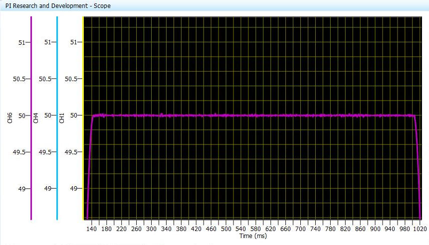 Oscilloscope trace from PI R&D showing the position stability of a piezo-driven stage after a step move. The smooth settling with no ringing contrasts sharply with the step-induced oscillations typical of stepper motor systems. Source: PI
Resolution Comparison with Real Products
Theoretical arguments become concrete when mapped to specific commercial products. The following comparison uses published specifications from major vendors, cross-referenced against independent measurements where available.
Stepper-Driven Stages
PI M-112.1DG (representative precision stepper stage):
- Travel: 25 mm
- Drive: NEMA 17 stepper with precision lead screw
- Maximum speed: 1.5 mm/s
- Minimum incremental motion (MIM): 0.05 um (50 nm) with 1/64 microstepping
- Unidirectional repeatability: 0.1 um
- Bidirectional repeatability: 1 um (backlash-limited)
- Cost: approximately $2,000 to $4,000 depending on configuration
The 50 nm MIM specification deserves scrutiny. This is measured unidirectionally, under controlled conditions, with optimal microstepping. Bidirectional repeatability is 20x worse at 1 um, revealing the backlash and friction floor that limits real-world positioning. In practice, this stage delivers reliable 1 um positioning with good unidirectional repeatability, but sub-micrometer bidirectional accuracy requires careful approach strategies.
Piezo-Driven Stages
SmarAct SLC-1720 (miniature ultrasonic piezo stage):
- Travel: 12 mm
- Maximum speed: >20 mm/s
- Resolution (closed-loop): <1 nm with nanometer encoder
- MIM: <1 nm
- Bidirectional repeatability: +/- 40 nm
- Blocking force: 3.5 N
- Mass: 13 g
- Cost: approximately $8,000 to $15,000
Nanomotion HR4 motor element (OEM component):
- Stall force: 15 to 18 N
- Maximum speed: 250 mm/s
- MIM: <10 nm
- Operating frequency: ultrasonic (inaudible)
- Speed range: 1 um/s to 250 mm/s (more than 5 decades of speed)
- Cost: motor element approximately $500 to $1,500; complete stage $3,000 to $8,000
PI N-664 NEXACT (ultra-high-precision piezo stage):
- Open-loop resolution: 0.03 nm
- Closed-loop MIM: 2 nm (with capacitive sensor)
- Travel: 30 mm
- Self-locking at rest (zero power hold)
- Cost: approximately $8,000 to $15,000
Xeryon XLS (compact rotary/linear piezo stage):
- Maximum speed: 1,000 mm/s
- Encoder resolution: 78 nm (Standard), down to 1 nm (Ultra)
- Self-locking at rest
- Operating frequency: 80 to 180 kHz
- Cost: approximately $2,000 to $6,000
Resolution Comparison Summary
| Product | Type | Travel | MIM | Bidir. Repeat. | Speed | Mass | Approx. Cost |
|---|---|---|---|---|---|---|---|
| PI M-112 | Stepper stage | 25 mm | 50 nm (unidir.) | 1 um | 1.5 mm/s | ~500 g | $2,000 to $4,000 |
| SmarAct SLC-1720 | Piezo stage | 12 mm | <1 nm | +/- 40 nm | >20 mm/s | 13 g | $8,000 to $15,000 |
| Nanomotion HR4 stage | Piezo stage | varies | <10 nm | <50 nm | 250 mm/s | varies | $3,000 to $8,000 |
| PI N-664 NEXACT | Piezo stage | 30 mm | 0.03 nm (OL) | <50 nm | moderate | ~200 g | $8,000 to $15,000 |
| Xeryon XLS | Piezo stage | varies | 1 to 78 nm | encoder-limited | 1,000 mm/s | compact | $2,000 to $6,000 |
The SmarAct SLC-1720 achieves 25x better bidirectional repeatability than the PI M-112 in a package that weighs 38 times less. The tradeoff is cost (2x to 4x higher) and travel (12 mm versus 25 mm).
 PI PILine U-521 ultrasonic linear stage: 18 mm travel, 200 mm/s peak speed, and sub-50 nm resolution. The direct-drive design eliminates lead screw backlash, pitch errors, and the coupling compliance that limit stepper-based stages. Source: PI
The Nanomotion HR4 operates across five decades of speed (1 um/s to 250 mm/s) while maintaining sub-10 nm MIM. No stepper motor can approach this. A stepper at 1 um/s is deep within its resonance zone and cannot maintain stable motion.
For a broader comparison of piezo motor architectures (traveling wave, standing wave, walking, inertia), see the piezo motion technologies compared overview.
Speed-Force Characteristics
Stepper Motor: Torque Falls Off a Cliff
Stepper motor torque drops steeply with increasing speed. The mechanism is the electrical time constant of the motor windings (L/R). As step rate increases, the current waveform in each phase has less time to reach its commanded value before the next commutation event. The current amplitude decreases, and with it, the torque.
A typical NEMA 23 motor rated at 300 Ncm holding torque might deliver:
| Speed (RPM) | Available Torque (Ncm) | Torque Retention | Linear Speed (5 mm screw) |
|---|---|---|---|
| 0 (hold) | 300 | 100% | 0 mm/s |
| 100 | 280 | 93% | 8.3 mm/s |
| 200 | 240 | 80% | 16.7 mm/s |
| 500 | 100 to 150 | 33 to 50% | 41.7 mm/s |
| 1,000 | 40 to 80 | 13 to 27% | 83.3 mm/s |
| 2,000 | 10 to 30 | 3 to 10% | 166.7 mm/s |
Above 500 RPM, usable torque has dropped by half to two-thirds. Above 1,000 RPM, most of the motor's rated torque is unavailable. High-voltage drivers (chopper drives operating at 24 to 80 V) push the torque curve higher by forcing current into the windings faster, but the fundamental L/R limitation remains.
This steep torque falloff means that a stepper motor dimensioned for adequate torque at speed must be massively oversized for the holding condition, where it will dissipate excess heat. Or, a motor sized for efficient holding will stall at moderate speeds under load.
Piezo Motor: Force Independent of Speed
Ultrasonic piezo motors produce force through friction coupling, and the available force is essentially independent of velocity up to the motor's speed limit. The Nanomotion HR4 delivers 15 to 18 N of stall force and maintains 12 to 15 N at speeds from 1 um/s to 250 mm/s.
This flat force-versus-speed characteristic means:
- The motor does not need to be oversized for any operating point within its speed range.
- There are no "torque dead zones" at particular speeds.
- Acceleration is uniform across the speed range (limited by force/mass ratio, not torque rolloff).
- The same motor handles slow precision scanning and fast repositioning without performance degradation.
Speed-Application Mapping
| Speed Range | Typical Application | Stepper Performance | Piezo Performance | Winner |
|---|---|---|---|---|
| <0.01 mm/s | Nanopositioning, interferometry | Resonance zone, unstable | Stable, sub-nm resolution | Piezo |
| 0.01 to 1 mm/s | Fiber alignment, probe microscopy | Resonance risk, vibration | Smooth, nanometer-class | Piezo |
| 1 to 10 mm/s | Optical inspection, metrology | Adequate with microstepping | Excellent | Piezo |
| 10 to 50 mm/s | Wafer probing, autofocus | Good (above resonance) | Good | Tie |
| 50 to 200 mm/s | Pick-and-place, PCB inspection | Good | At speed limit for some types | Stepper |
| >200 mm/s | Packaging, laser cutting | Excellent | Beyond most piezo limits | Stepper |
Thermal Behavior and Power at Hold
Stepper Motors: 100% Power Becomes Heat at Hold
A stepper motor at standstill is not idle. It requires full rated current in both phases to maintain holding torque and prevent step loss from external disturbances. This current flows through copper wire, and 100% of the electrical input becomes resistive heat.
For a NEMA 17 motor rated at 2 A per phase with 1.1 ohm per phase:
P_hold = 2 phases x I² x R = 2 x (2.0)² x 1.1 = 8.8 W
This is 8.8 watts of continuous heat dissipation, even when the motor is doing nothing. Motor case temperature reaches 50 to 70 degrees Celsius in free air. In an enclosed housing without active cooling, temperatures can exceed 90 degrees Celsius.
Thermal Dissipation Across Motor Sizes
| Motor | Rated Current (A) | Resistance (ohm) | Hold Power (W) | Case Temp in Free Air (C) |
|---|---|---|---|---|
| NEMA 11, 0.5 A | 0.5 | 6.0 | 3.0 | 45 to 55 |
| NEMA 14, 0.8 A | 0.8 | 3.5 | 4.5 | 50 to 60 |
| NEMA 17, 1.5 A | 1.5 | 2.1 | 9.5 | 55 to 70 |
| NEMA 17, 2.0 A | 2.0 | 1.1 | 8.8 | 50 to 70 |
| NEMA 23, 2.8 A | 2.8 | 1.5 | 23.5 | 65 to 90 |
| NEMA 34, 4.0 A | 4.0 | 0.6 | 19.2 | 60 to 80 |
Current reduction at standstill (dropping to 50 to 70% of rated current) reduces heat by 50 to 75%, but proportionally reduces holding torque and increases the risk of step loss from external vibration or gravity loads.
The Thermal Drift Problem
Heat does more than waste energy; it causes thermal expansion that directly degrades positioning accuracy. Consider two NEMA 17 motors in an enclosed microscope XY stage. Total hold power: 2 x 8.8 = 17.6 W. With a housing thermal resistance of ~1.5 C/W, the steady-state temperature rise is 26.4 C above ambient, bringing the housing to 48 C in a 22 C room.
With an aluminum frame (23 ppm/C) and a 150 mm optical path, a 15 C gradient produces 52 micrometers of thermal drift. For an instrument claiming 1 um accuracy, the motors have introduced 52x the target error while doing nothing.
Piezo Motors: Zero Power at Hold
Ultrasonic piezo motors consume zero electrical power at standstill. The friction preload between the ceramic tip and the guide rail holds the stage position passively, with no current, no heat, and no thermal drift. This is a fundamental physical difference, not an engineering optimization.
During motion, power consumption is typically 1 to 5 W for small and medium stages, far below stepper motors. The heat is generated intermittently (only while moving) and at a lower absolute level.
Thermal Comparison Summary
| Condition | Stepper (NEMA 17) | Piezo Motor | Impact on 100 mm Al Frame |
|---|---|---|---|
| Holding, full current | 8.8 W continuous | 0 W | Stepper: 10 to 20 um drift; Piezo: 0 |
| Holding, 50% current | 2.2 W continuous | 0 W | Stepper: 2 to 5 um drift; Piezo: 0 |
| Moving at 1 mm/s | 10 to 15 W | 2 to 4 W | Stepper: 12 to 25 um drift; Piezo: 2 to 5 um |
| 24-hour hold | 211 Wh dissipated | 0 Wh | Stepper: steady-state thermal gradient; Piezo: none |
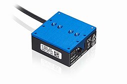
 PI N-565 NEXACT piezo stage. Zero electrical power at hold means zero heat, zero thermal drift, and unlimited hold time, a fundamental thermodynamic advantage over stepper motors that require continuous energization. Source: PI
For any application requiring thermal stability during extended hold periods (optical metrology, electron microscopy, semiconductor inspection), the stepper motor's continuous heat output is a fundamental liability. Mitigation (heat sinks, fan cooling, thermal isolation, liquid cooling) adds $50 to $500 per motor in hardware cost and introduces its own problems: fan vibration, airflow disturbance, plumbing complexity, condensation risk. These costs erode the stepper's price advantage. See the technology selection framework for a structured approach to evaluating these tradeoffs.
Closed-Loop Steppers: How Far Can They Go?
The emergence of closed-loop stepper systems has blurred the traditional servo/stepper boundary. Products like the Applied Motion StepSERVO (with 20,000 counts per revolution encoder) and the Nanotec SC4118 series add encoder feedback to stepper motors, enabling the controller to detect and correct lost steps in real time. Applied Motion claims 85% more usable torque below 750 RPM compared to open-loop operation, because the controller can push the motor harder without risk of undetected step loss.
What Closed-Loop Steppers Fix
-
Lost step detection and correction. The encoder verifies each step occurred. If the rotor falls behind, the controller increases current or reduces speed, eliminating cumulative drift.
-
Resonance management. The controller detects resonance oscillation and adjusts the drive waveform. Some drivers implement active damping by modulating current phase based on encoder feedback.
-
More aggressive acceleration. With step verification, the controller can push closer to the torque limit without open-loop safety margins.
What Closed-Loop Steppers Do NOT Fix
-
Mechanical step accuracy. The motor's tooth geometry produces +/- 5% per full step accuracy error (+/- 3 to 5 arc-minutes). This is a manufacturing tolerance in the iron laminations and magnetic circuit. The encoder can measure the error but cannot force the rotor past the electromagnetic detent to the ideal position. Interpolation between detent positions follows the same torque and accuracy limitations described in the microstepping section.
-
Vibration characteristics. The motor still operates by discrete detent positions. The step impulse excitation is unchanged. Closed-loop control reduces settling time but does not eliminate the impulse.
-
Detent torque and acoustic noise. Both are physical properties of the motor. Detent torque persists and produces cogging vibration. The motor still steps, still produces audible tones. Current profile optimization helps but cannot eliminate the fundamental.
-
Thermal behavior. Full current is still required for holding torque. Heat generation is unchanged.
The Verdict on Closed-Loop Steppers
Closed-loop steppers are a meaningful improvement for applications where occasional step loss was the primary concern. They push the useful stepper envelope from perhaps 5 um down to 2 to 3 um reliable positioning.
They do not transform a stepper into a different class of actuator. Discrete steps, detent torque, resonance, vibration, and thermal dissipation remain. For sub-micrometer resolution, sub-50 nm repeatability, zero vibration, or zero-power hold, the closed-loop stepper remains inadequate. It is a better stepper, not an alternative to direct-drive piezo.
Cost Comparison
The cost comparison between stepper and piezo is the most common objection to piezo adoption, and it deserves a nuanced treatment because the sticker price tells only part of the story.
Component-Level Cost
| Component | Stepper System | Cost Range |
|---|---|---|
| NEMA 17 motor | StepperOnline, OMC, Wantai | $5 to $50 |
| NEMA 23 motor | StepperOnline, Oriental Motor | $20 to $150 |
| Stepper driver (open-loop) | Allegro A4988, TI DRV8825, TMC2209 | $2 to $50 |
| Closed-loop stepper driver | Applied Motion StepSERVO, Nanotec | $150 to $500 |
| Lead screw + nut (standard) | Misumi, Thomson | $20 to $100 |
| Precision lead screw + anti-backlash nut | THK, NSK | $200 to $800 |
| Linear guide rail pair | Hiwin, THK | $50 to $300 |
| Coupling | Ruland, Helical | $15 to $80 |
| Component | Piezo System | Cost Range |
|---|---|---|
| Piezo motor element | Nanomotion, PI, SmarAct | $500 to $3,000 |
| Piezo motor controller | PI E-727, SmarAct MCS2 | $500 to $2,000 |
| Complete piezo linear stage | SmarAct SLC, Xeryon XLS | $2,000 to $15,000 |
| Complete piezo linear stage | PI PILine, PI NEXACT | $5,000 to $15,000 |
System-Level Cost at Different Resolution Targets
The true comparison requires matching the systems to the same performance specification:
| Resolution Target | Stepper System Cost | What You Need | Piezo System Cost | What You Get |
|---|---|---|---|---|
| 10 um | $100 to $300 | NEMA 17 + driver + screw | N/A (overkill) | N/A |
| 5 um | $200 to $500 | NEMA 17 + 1/8 step + precision screw | $2,000 to $4,000 | SmarAct or Xeryon basic |
| 1 um | $500 to $1,500 | NEMA 17 + 1/32 step + precision screw + tuning | $3,000 to $6,000 | Xeryon XLS or PI PILine |
| 0.5 um | $1,500 to $3,000 | Stepper + encoder + closed-loop + anti-backlash | $4,000 to $8,000 | Standard piezo stage |
| 0.1 um | $3,000 to $5,000 | Stepper + linear encoder + closed-loop + thermal mgmt | $5,000 to $10,000 | PI NEXACT or SmarAct |
| 0.01 um | Not achievable | N/A | $8,000 to $15,000 | PI N-664 NEXACT |
| 0.001 um | Not achievable | N/A | $10,000 to $20,000 | Ultra-precision piezo |
Hidden Costs That Close the Gap
When targeting 0.5 to 2 um resolution (the gray zone), the stepper system accumulates costs that are not reflected in the motor price:
| Hidden Cost | Stepper System | Piezo System |
|---|---|---|
| External linear encoder | $300 to $1,500 | Included |
| Closed-loop driver upgrade | $150 to $500 | Standard |
| Anti-backlash lead screw nut | $100 to $400 | N/A (direct drive) |
| Thermal management hardware | $50 to $300 | $0 |
| Vibration isolation from motor | $100 to $500 | $0 |
| Resonance avoidance (dampers, profiling) | $50 to $200 | $0 |
| Integration and tuning labor (at $100/hr) | $800 to $1,600 (8 to 16 hours) | $200 to $400 (2 to 4 hours) |
| Total hidden costs | $1,550 to $5,000 | $200 to $400 |
At 1 um resolution: the "cheap" stepper axis costs $2,050 to $6,500 total. The "expensive" piezo stage costs $3,200 to $6,400 total. The cost gap has collapsed, and the piezo system delivers better vibration, noise, thermal, and reliability performance.
The cost crossover is approximately 1 to 2 um resolution. Above 5 um, steppers win on cost unambiguously. Below 0.5 um, only piezo can deliver, and the cost question is moot. Between 1 and 5 um, the answer depends on the specific application's secondary requirements (vibration, noise, thermal, size, vacuum compatibility).
Application Decision Scenarios
Scenario 1: 3D Printer / Desktop CNC
Requirements: 300 mm XY travel, 50 um layer height, 100 mm/s print speed, $200 budget per axis, open-source controller compatibility.
Analysis: Resolution (50 um) is 50x coarser than a stepper's floor. Speed (100 mm/s) exceeds most piezo motors. Budget ($200) is 10x below entry-level piezo. The open-source ecosystem (Marlin, Klipper, grbl) is built for stepper interfaces.
Winner: Stepper motor, decisively. A NEMA 17 with GT2 belt or lead screw delivers the performance at the price.
Scenario 2: Confocal Microscopy Autofocus
Requirements: 10 mm Z-travel, 100 nm positioning resolution, <50 nm vibration during imaging, silent operation in laboratory, hold at focus position for 30-second exposure, compact (fits under objective turret).
Analysis: The 100 nm resolution is below the stepper's reliable microstepping floor (0.5 to 1 um). The vibration requirement (<50 nm) eliminates steppers entirely (stepper detent vibration alone is 300+ nm). Silent operation rules out full-step or even moderate microstepping. The 30-second hold requires either continuous stepper current (generating heat under the objective, causing thermal focus drift) or a brake mechanism. Compactness favors the SmarAct SLC-1720 at 13 g versus a NEMA 17 stepper assembly at ~500 g.
Winner: Piezo motor, clearly. A SmarAct SLC-series stage or PI PILine stage meets all requirements. The stepper fails on resolution, vibration, noise, and thermal, four of the six requirements.
Scenario 3: Fiber Optic Alignment (Photonic Packaging)
Requirements: 6 mm XYZ travel, <5 nm positioning resolution, <50 nm bidirectional repeatability, hold during 10-minute adhesive cure, non-magnetic (fiber Bragg grating sensor nearby), vacuum-compatible variant available.
Analysis: At 5 nm resolution and 50 nm repeatability, there is no stepper motor solution. Microstepping cannot reach 5 nm. Even closed-loop steppers with external encoders top out around 500 nm reliable repeatability due to lead screw backlash. The non-magnetic requirement disqualifies all electromagnetic motors (stepper and servo alike). The vacuum requirement eliminates grease-lubricated lead screws. Zero-power hold is essential during the cure cycle to avoid thermal disturbance to the adhesive.
Winner: Piezo motor, the only viable option. A 3-axis SmarAct SLC system with nanometer encoders, crossed-roller bearings, and optical encoders (no magnetic components). Cost: $15,000 to $30,000 for the complete 3-axis system. There is no stepper-based system at any price that meets these requirements.
Scenario 4: High-Speed Pick-and-Place Assembly
Requirements: 400 mm XY travel, 500 mm/s slew speed, 25 um placement accuracy, 50 ms settle time, 24/7 industrial operation, 5-year maintenance interval, cost-sensitive (high volume manufacturing).
Analysis: The 500 mm/s speed exceeds most piezo motors. The 25 um accuracy is easily achievable with microstepped steppers. The 24/7 duty cycle and 5-year maintenance interval favor proven industrial infrastructure. The 400 mm travel is beyond most piezo stages.
Winner: Stepper motor (or servo for higher throughput). A NEMA 23 with ball screw and 1/8 microstepping delivers the accuracy at the speed for $300 to $800 per axis.
Practical Recommendations
Choose a Stepper Motor When:
- Speed exceeds 50 mm/s sustained. Stepper torque drops but remains adequate for most loads above resonance.
- Budget is below $500 per axis. No piezo solution exists at this price.
- Resolution of 5 um or coarser is acceptable. Microstepping delivers this reliably at 1/8 to 1/16.
- Open-loop simplicity is valued. No encoder, no tuning, no servo loop.
- The controller ecosystem matters. Steppers integrate with thousands of off-the-shelf drivers, controllers, and software packages.
- Force exceeds 20 N. Stepper plus lead screw produces hundreds of newtons easily.
- Duty cycle is high. Steppers handle continuous operation for tens of thousands of hours with minimal maintenance.
Choose a Piezo Motor When:
- Resolution below 1 um is required. Microstepping cannot reliably deliver this. Piezo motors routinely achieve 1 to 50 nm.
- Vibration must be minimized. Ultrasonic drive frequency (20 to 200 kHz) does not excite mechanical structures. Optical metrology, microscopy, and scanning probe applications demand this.
- Acoustic noise must be inaudible. Piezo motors are silent at all operating speeds.
- Zero-power hold is needed. Self-locking friction hold with no current, no heat, no thermal drift. Essential for long-hold applications and thermally sensitive environments.
- The environment is vacuum, cleanroom, or cryogenic. Piezo motors generate no particles, no outgassing from lubricants, and no heat at hold. They operate across wide temperature ranges.
- Non-magnetic operation is required. Piezo motors have no permanent magnets and no current-carrying coils (during hold). Essential near electron beams, SQUIDs, fiber Bragg gratings, and MRI systems.
- Size and weight are critical. The SmarAct SLC-1720 weighs 13 g. A comparable stepper stage weighs 500 g. This matters for multi-axis systems, tip-tilt platforms, and any application where the actuator mass affects the controlled system's dynamics.
- Bidirectional repeatability below 100 nm is required. No lead screw system, regardless of anti-backlash measures, can match the <50 nm bidirectional repeatability of a direct-drive piezo stage.
The Decision Boundary
The boundary between stepper and piezo is not a single line; it is a zone defined by multiple parameters. But a simplified decision rule covers most cases:
If all you need is > 5 um resolution, > 50 mm/s speed, and < $500/axis, the stepper wins. It is simpler, cheaper, and proven. Do not overthink this.
If you need < 1 um resolution, or zero vibration, or zero-power hold, the piezo wins. The stepper cannot physically deliver these, regardless of microstepping ratio, closed-loop feedback, or driver sophistication.
Between 1 and 5 um, evaluate the secondary factors. If the application requires vacuum compatibility, non-magnetic operation, silent running, compact size, or thermal stability, the piezo motor's advantages accumulate until the higher price is justified. If none of those factors matter, the stepper is still the more economical path.
The technology selection framework provides a structured decision matrix for navigating this boundary. The piezo vs. servo comparison covers the higher-performance end of the spectrum, where direct-drive linear servos compete with piezo motors. For details on piezo motor wear and lifetime in production environments, see the dedicated article.
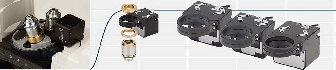 Piezo-driven autofocus stages for microscopy: a quintessential "piezo territory" application. The compact Z-focus mechanism delivers 100 nm resolution, zero vibration during imaging, and silent operation, all requirements that stepper motors cannot meet. Source: PI