Fundamentals
Resonant frequency, stator design, and what determines motor bandwidth
How the geometry and material properties of a piezoelectric stator define its vibration modes, operating frequency, and dynamic response
Why resonance is not optional
A piezoelectric ceramic element driven off-resonance produces displacements measured in tens of nanometers. That is useful for precision positioning but far too small to drive a friction-based motor at meaningful speeds. Operating at mechanical resonance amplifies the vibration amplitude by the mechanical quality factor Qm, which typically ranges from 500 to 2000 in motor-grade stators. This transforms 30 nm of intrinsic displacement into 15 to 60 micrometers of surface motion, enough to propel a rotor or slider at speeds of hundreds of millimeters per second.
This amplification is not free. It comes with constraints. The motor must be driven at a specific frequency (or narrow band of frequencies), the stator geometry must be designed to place the desired vibration mode at the target frequency, and the system bandwidth is fundamentally limited by the sharpness of the resonance. Understanding these constraints is the key to designing stators that work and diagnosing those that do not.
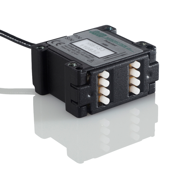
Image: Nanomotion Ltd.
Mechanical resonance in metal-ceramic composites
An ultrasonic motor stator is not a monolithic piece of PZT. It is a composite structure: one or more PZT elements bonded to a metal substrate (the stator body), typically made of phosphor bronze, stainless steel, aluminum alloy, or a copper-beryllium alloy. The metal serves multiple functions. It provides structural rigidity, carries the friction contact surface, conducts heat away from the ceramics, and its geometry shapes the vibration mode.
The resonant behavior of this composite is governed by the same physics as any vibrating structure, but with complications arising from the material mismatch:
PZT properties: Density approximately 7600 kg/m3, Young's modulus approximately 60 to 80 GPa (direction-dependent), Poisson's ratio approximately 0.31. The elastic properties change with electric field (piezoelectric stiffening) and with frequency.
Metal substrate properties (phosphor bronze example): Density approximately 8800 kg/m3, Young's modulus approximately 110 GPa, Poisson's ratio approximately 0.33. These properties are largely independent of frequency in the ultrasonic range.
The effective stiffness and mass of the composite determine its natural frequencies. Because PZT is softer than most metals used for stator bodies, adding ceramic to a metal structure lowers the resonant frequency compared to the metal alone, by a factor that depends on the ceramic-to-metal thickness ratio.
The bond layer matters
The PZT is bonded to the metal stator body using either epoxy adhesive or soldering. This bond layer, typically 5 to 30 micrometers thick, has a disproportionate influence on performance. A compliant or lossy bond layer:
- Reduces the effective coupling between the ceramic and the stator (less of the ceramic's strain transfers to the stator surface).
- Introduces additional mechanical damping, lowering Qm.
- Can degrade under sustained high-amplitude vibration, causing progressive performance loss.
High-performance stators often use soldered bonds (with tin-silver or indium-based solders) rather than epoxy, because solder is stiffer and more thermally conductive. The trade-off is that soldering requires more careful process control and limits the maximum operating temperature.
Modal analysis fundamentals
Every structure has an infinite set of natural vibration modes, each with a characteristic frequency and shape. For ultrasonic motor stators, only a few modes are useful; the rest are parasitic. The job of stator design is to place the desired mode at the target frequency while pushing parasitic modes far enough away that they do not interfere.
What a vibration mode looks like
A vibration mode is defined by its mode shape (the spatial pattern of displacement) and its natural frequency. For common stator geometries:
Annular (ring) stators used in traveling-wave rotary motors exhibit circumferential bending modes characterized by the number of nodal diameters. A mode with n nodal diameters is called the B(0,n) mode. The classic Shinsei USR-60 motor uses the B(0,9) mode, with 9 nodal diameters, operating near 40 kHz.
Rectangular plate stators used in many linear motors exhibit bending modes along their length and width, labeled B(m,n) where m and n are the numbers of nodal lines in each direction. A common design uses the B(2,1) mode or B(3,1) mode to generate elliptical surface motion.
Bar (beam) stators used in some linear motors exhibit longitudinal (L) and bending (B) modes. Designs that combine a longitudinal mode with a bending mode at the same frequency create the elliptical tip motion needed for friction drive.
Finite element analysis is the standard design tool
While analytical solutions exist for simple geometries (uniform beams, thin rings), practical stator designs require finite element analysis (FEA). The standard workflow is:
- Create a 3D model of the stator including the metal body, PZT elements, electrodes, and bond layers.
- Define material properties: piezoelectric, elastic, dielectric, and density tensors for the PZT; elastic properties for the metal and bond layer.
- Run a modal analysis to find natural frequencies and mode shapes.
- Identify the desired mode and note its frequency.
- Iterate the geometry to place that mode at the target frequency.
- Run a harmonic analysis to predict vibration amplitude, surface velocity, and impedance at the operating frequency.
- Validate against measurements on prototype stators.
COMSOL Multiphysics and ANSYS are the most widely used FEA packages for piezoelectric stator design. Both handle the coupled electromechanical problem natively. Open-source alternatives (e.g., Elmer FEM) can also solve piezoelectric problems but with less mature preprocessing and post-processing tools.
How stator geometry sets the resonant frequency
The resonant frequency of a stator depends on its geometry, material properties, and boundary conditions. The relationships are intuitive once you understand the underlying physics.
Thickness and frequency
For thickness-mode vibration of a plate, the resonant frequency is:
f = v / (2t)
where v is the sound velocity in the material and t is the thickness. For PZT-4, the longitudinal sound velocity is approximately 4600 m/s, so a 1 mm thick disc has a thickness-mode resonance near 2.3 MHz. This is far above typical ultrasonic motor operating frequencies (20 to 200 kHz).
Most ultrasonic motors use bending modes, not thickness modes. Bending-mode frequencies are much lower for the same thickness because bending stiffness scales differently.
Length, width, and bending modes
For a uniform beam of length L, thickness h, and material with Young's modulus E and density rho, the nth bending mode frequency is approximately:
f_n = (lambda_n^2 / (2 * pi)) * (h / L^2) * sqrt(E / (12 * rho))
where lambda_n is a dimensionless constant depending on the boundary conditions (e.g., lambda_1 = 4.73 for a free-free beam). The key scaling relationships:
- Frequency scales as h/L^2. Doubling the length drops the frequency by a factor of 4. Doubling the thickness doubles the frequency. This gives designers a large tuning range through geometry.
- Frequency scales as sqrt(E/rho). Stiffer materials vibrate faster. Denser materials vibrate slower. Since PZT has moderate stiffness but high density, adding PZT to a stator lowers the frequency.
- Higher-order modes have higher frequencies, with spacing that increases as n^2.
Ring stator sizing
For an annular ring stator with mean radius R, the circumferential bending mode B(0,n) has a frequency that scales approximately as:
f ~ (n^2 * h) / R^2
This means larger rings have lower operating frequencies. The Shinsei USR-60, with an outer diameter of 60 mm, operates near 40 kHz. Scaling it down to 30 mm diameter would push the same mode to approximately 160 kHz, which is above the practical range for many drive electronics and begins to encounter problems with increased air damping and tighter manufacturing tolerances.
Teeth and structural features
Many stator designs include teeth or slots machined into the metal surface. These serve two purposes: they amplify the tangential (in-plane) component of surface motion to improve friction drive efficiency, and they provide discrete contact points that can be optimized for the desired contact mechanics. Teeth also modify the resonant frequency and mode shape significantly. Adding teeth effectively reduces the local stiffness near the contact surface, lowering the resonant frequency and modifying the ratio of normal to tangential displacement. FEA is essential for predicting the effect of tooth geometry.
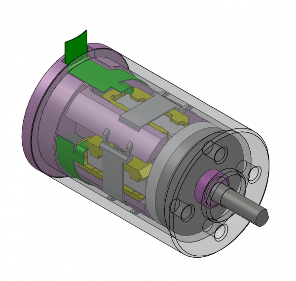
Image: Nanomotion Ltd.
The relationship between resonant frequency and bandwidth
This is where stator design connects directly to motor dynamic performance. The bandwidth of a resonant system is inversely proportional to its quality factor:
BW = f_res / Qm
For a stator with a resonant frequency of 40 kHz and Qm of 1000, the 3 dB bandwidth is 40 Hz. This means the vibration amplitude drops to 70.7% of its peak value just 20 Hz above or below the resonant frequency.
This narrow bandwidth has profound implications:
Frequency tracking is mandatory
The resonant frequency of a stator shifts during operation due to:
- Temperature changes. The elastic moduli of PZT decrease with increasing temperature (typically -0.3% to -0.5% per degree C), shifting the resonance downward. This is explored in depth in the article on thermal behaviour. A 20 C temperature rise can shift a 40 kHz resonance by 200 to 400 Hz, well outside the 40 Hz bandwidth.
- Preload changes. The normal force pressing the rotor against the stator modifies the boundary conditions and shifts the resonance, typically upward by tens to hundreds of Hz depending on the preload mechanism compliance.
- Wear. As the friction surface wears (see life expectancy and wear mechanisms), the stator geometry changes slightly, shifting the resonance. This is a slow effect (thousands of hours) but matters for lifetime prediction.
- Aging. PZT properties drift logarithmically with time after poling, causing a slow upward frequency drift (typically less than 1% over the motor's lifetime).
The drive electronics must track these shifts in real time. The most common approaches are:
Phase-locked loop (PLL). Monitors the phase relationship between the drive voltage and the stator current. At resonance, the current leads the voltage by 90 degrees for a series-resonant circuit (or lags by 90 degrees for parallel resonance). The PLL adjusts the drive frequency to maintain this phase relationship. This is the standard approach for traveling-wave motors.
Admittance tracking. Monitors the electrical admittance of the stator and drives at the frequency of maximum admittance (or maximum conductance). More robust than simple phase tracking because it is less sensitive to parasitic capacitance.
Swept-frequency search. Periodically sweeps a range of frequencies to locate the resonance peak, then locks onto it. Used during startup or when the resonance has shifted by more than the PLL can track.
Bandwidth sets the speed control range
In many ultrasonic motor designs, speed is controlled by varying the drive frequency slightly above resonance. The vibration amplitude (and therefore the motor speed) decreases as the frequency moves away from resonance. The usable speed control range is limited by the bandwidth: driving too far above resonance collapses the vibration amplitude to unusable levels.
For a Qm of 1000, the practical speed control range via frequency tuning is narrow, perhaps 2:1 or 3:1 at best. Wider speed ranges require voltage amplitude control, pulse-density modulation, or phase control between two-phase drive signals.
Bandwidth limits step response
The step response of a resonant system is governed by the ring-up time:
tau = Qm / (pi * f_res)
For f_res = 40 kHz and Qm = 1000, tau = 8 ms. The stator needs approximately 3 to 5 time constants (24 to 40 ms) to reach full amplitude after the drive signal is applied. This sets a fundamental limit on motor bandwidth, particularly for dynamic servo applications requiring fast acceleration or rapid direction changes.
Lower Qm enables faster dynamic response but at the cost of reduced displacement amplification and increased heating. This is the central design trade-off in stator design: high Qm for efficiency and displacement amplitude versus low Qm for bandwidth and dynamic response.
Ring-down and braking time
The same time constant that governs ring-up also governs ring-down when the drive is removed. After the drive signal stops, the stator continues to vibrate for 3 to 5 time constants. During this ring-down period, the motor continues to produce force (though decreasing), which complicates braking and can cause overshoot in positioning applications. For a 40 kHz stator with Qm = 1000, the ring-down takes 24 to 40 ms, meaning the motor cannot stop faster than this regardless of the control system's response time. Active braking techniques (applying a drive signal phase-shifted to oppose the existing vibration) can reduce ring-down by a factor of 2 to 3 but require real-time knowledge of the vibration phase.
Practical implications for control loop design
The motor's mechanical bandwidth, as set by the stator's resonant characteristics, directly constrains the achievable servo bandwidth.
Update rate requirements
The servo control loop must run significantly faster than the motor's mechanical bandwidth to maintain stability. A common rule of thumb: the control loop sample rate should be at least 10x the desired closed-loop bandwidth. If the motor's mechanical bandwidth supports closed-loop positioning bandwidth up to 100 Hz, the control loop needs to run at 1 kHz or faster.
For high-performance systems targeting bandwidths of 500 Hz to 1 kHz, control update rates of 5 to 10 kHz are necessary. This is well within the capability of modern digital controllers but requires attention to computational latency, sensor update rates, and communication delays.
Frequency and amplitude control interaction
Most ultrasonic motor controllers must manage two coupled control loops:
-
Frequency control (inner loop). Tracks the stator resonance using PLL or admittance feedback. This loop must be fast (update rate matching or exceeding the drive frequency, typically 40+ kHz) and is usually implemented in analog hardware or FPGA.
-
Position/velocity control (outer loop). Commands the motor speed or position via voltage amplitude, phase, or frequency offset. This loop runs at the servo rate (1 to 10 kHz typically) and can be implemented in a digital microcontroller.
The interaction between these loops can cause stability problems if not properly managed. Changes in the frequency control loop (in response to resonance shifts) affect the motor's speed transfer function, which the position controller must accommodate.
Designing for dynamic performance
If your application requires fast dynamic response:
-
Choose a higher resonant frequency. Higher f_res means faster ring-up for the same Qm, and the absolute bandwidth (in Hz) is larger. A 100 kHz stator with Qm = 500 has a bandwidth of 200 Hz and a ring-up time constant of 1.6 ms. Much faster than the 40 kHz example above.
-
Accept lower Qm. Intentionally increasing damping (through material selection, bond layer properties, or stator geometry) widens bandwidth at the cost of efficiency. For servo applications, a Qm of 200 to 500 may be preferable to 1000+.
-
Use voltage amplitude control for speed. This responds faster than frequency tuning because it does not fight the resonance envelope.
-
Consider multi-mode designs. Some advanced stator designs exploit two closely spaced modes, enabling broader-band operation. This is an active research area with commercial implementations in some precision-stage motors.
Stator material selection
The choice of metal for the stator body significantly influences resonant behavior:
| Material | Density (kg/m3) | Young's modulus (GPa) | v_sound (m/s) | Notes |
|---|---|---|---|---|
| Phosphor bronze | 8800 | 110 | 3540 | Traditional choice, good machinability |
| Stainless steel 304 | 8000 | 193 | 4910 | Higher frequency for same geometry |
| Aluminum 7075 | 2810 | 72 | 5060 | Light, high sound velocity, lower Qm |
| Beryllium copper | 8250 | 131 | 3980 | Good fatigue life, expensive |
| Titanium Ti-6Al-4V | 4430 | 114 | 5070 | Light, biocompatible, difficult to machine |
Phosphor bronze remains the most common choice because it offers a good balance of acoustic properties, machinability, corrosion resistance, and cost. Aluminum is used when low mass is critical (e.g., camera autofocus motors). Stainless steel appears in applications requiring chemical resistance.
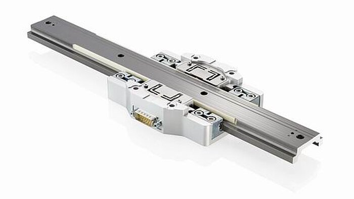
Image: PILine U-264 OEM rectangular plate stator drive module. The stator body (white/grey block) contains PZT elements bonded to a phosphor bronze or stainless steel substrate. Two ceramic friction tips contact the drive rod. Source: PI
Manufacturing tolerances and frequency scatter
One of the most frustrating realities of stator manufacturing is frequency scatter. Nominally identical stators will have slightly different resonant frequencies due to:
- PZT property variation. Batch-to-batch variation in piezoelectric and elastic properties, even from the same supplier, can shift the resonance by 1% to 2%.
- Dimensional tolerances. A 10-micrometer variation in stator thickness changes the resonance by approximately 0.5% for a typical bending-mode stator.
- Bond layer thickness variation. Difficult to control precisely, especially with epoxy adhesives.
- Assembly stress. Clamping or mounting stresses modify the effective boundary conditions.
For a 40 kHz stator, a 2% frequency scatter means a range of 39.2 to 40.8 kHz across a production batch. The drive electronics must accommodate this range, and for two-phase motors where two stator modes must be degenerate (identical frequency), matching becomes critical. Traveling-wave motors typically require the two driven modes to be within 0.1% to 0.5% of each other, which often necessitates post-manufacturing frequency trimming (selective material removal to tune the frequency).
Worked example: sizing a rectangular plate stator
Consider a design requirement for a linear motor operating near 40 kHz with a bending-mode stator. The target is a B(3,1) mode in a phosphor bronze plate with bonded PZT.
Step 1: initial length estimate. For a free-free beam, the third bending mode (n=3) has lambda_3 = 7.855. For phosphor bronze (E = 110 GPa, rho = 8800 kg/m^3), with a plate thickness h = 2.5 mm:
f_3 = (7.855^2 / (2 * pi)) * (h / L^2) * sqrt(E / (12 * rho))
Solving for L at f_3 = 40 kHz:
L^2 = (7.855^2 / (2 * pi * 40000)) * 0.0025 * sqrt(110e9 / (12 * 8800))
This gives L approximately 25 mm. The metal-only stator at this length resonates near 40 kHz in the B(3,1) mode.
Step 2: account for PZT. Adding a PZT layer (typically 0.5 to 1.0 mm thick) bonded to one face increases the composite mass more than it increases stiffness, because PZT is denser (7600 kg/m^3) but softer (60 to 80 GPa) than phosphor bronze. The resonant frequency drops by approximately 10 to 20% depending on the PZT-to-metal thickness ratio. To compensate, either reduce the length to approximately 22 to 23 mm or increase the metal thickness to restore stiffness relative to the added mass.
Step 3: FEA verification. Build the composite model in COMSOL or ANSYS. The actual B(3,1) frequency will differ from the beam approximation by 5 to 15% because the plate has finite width (the beam formula ignores width effects) and the boundary conditions of the real stator differ from the idealized free-free case. Iterate the length in 0.5 mm increments until the desired mode falls within 1% of 40 kHz.
Step 4: check mode separation. The B(2,1) and B(4,1) modes will bracket the B(3,1) target. For clean operation, these parasitic modes should be at least 10% away in frequency. If they are too close, adjust the width-to-length ratio or add slots to shift the parasitic modes.
Step 5: prototype and measure. Build 5 to 10 stators from the first manufacturing batch. Measure the resonant frequency of each using an impedance analyzer (e.g., Agilent 4294A or equivalent). Expect a spread of 1 to 2% around the mean. If the mean deviates from the target by more than 1%, adjust the geometry for the next batch.
Frequency trimming techniques
When production stators do not hit the target frequency, several post-manufacturing techniques can adjust the resonance:
Material removal (frequency increase). Removing mass from the stator surface raises the resonant frequency. Laser ablation, precision grinding, or chemical etching can remove 10 to 50 micrometers of metal from specific locations. Removing material near a displacement antinode has the greatest effect. A 10-micrometer removal from a 2.5 mm stator shifts the frequency upward by approximately 0.4%.
Mass addition (frequency decrease). Adding mass lowers the frequency. Small drops of UV-curable adhesive or solder bumps placed at displacement antinodes can bring an overshooting frequency down. This is less common than material removal because it introduces potential reliability concerns (adhesive degradation, particle risk).
Electrode patterning. In some designs, altering the electrode pattern (by laser trimming or masking) changes the effective coupling and shifts the apparent resonance as seen by the drive electronics. This does not change the mechanical resonance but shifts the frequency of maximum admittance.
Preload adjustment. Changing the mechanical preload between the stator and rotor/slider shifts the resonance, typically upward. This is not a manufacturing trim but an assembly parameter. The preload spring stiffness and its coupling to the stator mode must be characterized so that the assembly preload targets the correct frequency.
Temperature compensation in drive electronics
Because the resonant frequency shifts with temperature (see thermal behaviour), the drive electronics must continuously adapt. The key parameters for the frequency tracking loop:
Lock range. The frequency range over which the tracking loop can maintain lock without losing the resonance. A well-designed PLL or admittance tracker should have a lock range of at least 2% of the nominal frequency to accommodate the full operating temperature range.
Capture range. The range from which the tracking loop can initially acquire the resonance. This must be wider than the lock range, typically 3 to 5% of nominal, to accommodate unit-to-unit frequency scatter plus temperature offset at startup.
Tracking speed. How fast the loop can follow a changing resonance. During rapid thermal transients (e.g., motor startup from cold), the frequency may shift at 10 to 50 Hz per second. The tracking loop must follow this without losing lock.
Phase margin. The tracking loop interacts with the mechanical resonance to form a coupled electromechanical feedback system. Insufficient phase margin causes oscillation around the resonant frequency, producing audible buzzing and reduced motor performance. Typical designs target 30 to 45 degrees of phase margin.
| Operating scenario | Frequency shift | Tracking requirement |
|---|---|---|
| Room temperature, warmed up | Baseline | Static lock |
| 0 to 60 C operating range | -1.5% to +0% | Slow tracking (0.1 Hz/s) |
| Motor startup (cold to hot in 30 s) | -1% in 30 s | Fast tracking (30 Hz/s) |
| Preload change (manual adjustment) | +0.5% step | Step response < 100 ms |
| Production unit variation | +/- 2% | Wide capture range |
Modal coupling and parasitic modes
A stator designed for a specific operating mode invariably has many other resonant modes at nearby frequencies. These parasitic modes can degrade motor performance if they are excited unintentionally, and managing them is a critical part of stator design.
Mode coupling mechanisms
Parasitic modes are excited through several mechanisms:
- Drive asymmetry. If the PZT electrodes do not couple purely to the desired mode, a fraction of the drive energy excites neighboring modes. For a rectangular plate in the B(3,1) mode, the B(1,3) and B(2,2) modes may have partial electrode coupling.
- Structural asymmetry. Manufacturing tolerances that break the stator's symmetry (uneven PZT thickness, off-centre bonding, non-uniform preload) split degenerate modes and create coupling between modes that should be orthogonal.
- Nonlinear effects. At high drive amplitudes, the piezoelectric material's nonlinearity generates harmonics and intermodulation products that can excite modes at multiples or combinations of the drive frequency.
- External loads. The contact force between stator and rotor changes the boundary conditions and can couple energy from the driven mode into parasitic modes. This effect is load-dependent: a motor may run smoothly at low load but exhibit anomalous vibrations at high load as parasitic modes are excited.
Identifying parasitic modes
The primary tool for identifying parasitic modes is impedance analysis. Sweeping the drive frequency while measuring the electrical impedance (magnitude and phase) reveals all electromechanically coupled resonances. Each resonance appears as a minimum in impedance magnitude (series resonance) followed by a maximum (parallel resonance). The separation between these extremes indicates the coupling strength of each mode.
For a well-designed stator, the impedance plot shows the desired mode as a strong, well-separated resonance with weak parasitic modes at least 10% away in frequency. A problematic stator shows parasitic modes close to the operating frequency or modes with coupling strength comparable to the primary mode.
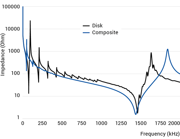
Image: Electrical impedance magnitude versus frequency for a bare PZT disc (black) and a composite piezo-metal structure (blue). The composite stator shows a strongly isolated primary resonance near 1400 kHz with the parasitic modes suppressed relative to the bare disc, demonstrating the mode-selection effect of the metal stator body. Source: PI Ceramic
Design strategies for mode separation
Several geometric modifications improve mode separation:
-
Aspect ratio tuning. For rectangular plates, adjusting the length-to-width ratio shifts the frequency relationship between bending modes in different directions. An aspect ratio of 3:1 to 4:1 typically provides good separation between the primary longitudinal bending mode and transverse modes.
-
Asymmetric slots. Narrow slots cut perpendicular to the stator's length at specific locations can suppress unwanted modes without significantly affecting the primary mode. The slot locations correspond to strain antinodes of the parasitic mode.
-
Mass loading at specific points. Small added masses at the antinodes of parasitic modes shift them downward in frequency without affecting the primary mode (if placed at its nodal lines). This technique is used in production tuning of traveling-wave motors.
-
Composite stator construction. Using different materials or thicknesses in different regions of the stator creates deliberate impedance mismatches that reflect parasitic mode energy while transmitting the primary mode. This approach is used in some high-performance Langevin transducer designs.
Mode interaction during operation
Even when parasitic modes are well separated at room temperature and zero load, they can approach the operating frequency under certain conditions. Temperature changes shift all modes, but not equally; some modes have stronger temperature coefficients than others because they couple differently to the PZT properties. A mode that is safely 15% above the operating frequency at 25 °C may drift to within 5% at 80 °C, close enough to cause audible noise and force ripple.
The practical solution is to map all nearby modes across the full operating temperature and load range during the design validation phase. Any mode that comes within 5% of the operating frequency must be addressed through redesign or accepted as a limitation of the operating envelope.
Summary of design relationships
To consolidate the key dependencies:
- Stator size up = frequency down, force capacity up, speed capacity up, motor size up.
- Stator thickness up = frequency up (for bending modes), stiffness up.
- PZT fraction up = coupling up, frequency down (PZT is denser and softer than most metals).
- Qm up = amplitude up, efficiency up, bandwidth down, ring-up time up.
- Frequency up = bandwidth up (for same Qm), smaller stator, tighter tolerances, faster dynamics.
- Teeth added = tangential motion amplified, frequency modified, mode shape altered.
- Parasitic modes close = noise, force ripple, efficiency loss. Maintain at least 10% frequency separation.
- Higher drive voltage = more amplitude, but nonlinear effects and parasitic mode excitation increase above 50% of the depoling field.
These relationships are not independent. Changing one parameter often affects several others. For example, increasing stator thickness to raise the frequency also increases mass and stiffness, which changes the Qm and the coupling coefficient. The design process is inherently iterative, starting from the analytical estimates described above, refining through FEA, and validating through prototype testing. A typical stator design requires three to five design iterations from initial concept to production-ready geometry.
These relationships are coupled and often competing. Stator design is fundamentally an optimization problem with multiple constraints, and understanding the physics behind these couplings is essential to navigating the trade-space effectively.