Fundamentals
Power electronics for piezo motors: drive voltage, current, and controller integration
AC excitation, voltage levels, power factor, third-party controller integration, and battery operation
An ultrasonic piezo motor is not a simple DC device. It requires a high-frequency AC drive signal, precisely tuned to the stator's mechanical resonance, at voltage levels that range from 10 V to 200 V peak depending on the motor design. The drive electronics are as important to system performance as the motor itself; poor driver design can halve motor force, triple power consumption, or destroy the PZT through overvoltage. The specifications explained article covers how datasheet numbers relate to real-world driver requirements. This article covers the electrical requirements of ultrasonic piezo motors and the practical considerations for integrating them into motion control systems.

Image: Physik Instrumente (PI)
Electrical model of an ultrasonic piezo motor
Before discussing drive circuits, it is essential to understand what the drive electronics "see" when connected to a piezo motor. The electrical behaviour of a piezo motor near resonance is described by the Butterworth-Van Dyke (BVD) equivalent circuit:
- C₀ (static capacitance): The PZT element behaves as a capacitor at frequencies away from resonance. Typical values range from 1 nF to 100 nF depending on element size and number. This capacitance must be charged and discharged every AC cycle, drawing reactive current.
- L₁, C₁, R₁ (motional branch): A series RLC circuit representing the mechanical resonance. L₁ and C₁ set the resonant frequency; R₁ represents mechanical losses (internal friction, radiation to the load, and dielectric losses).
- At resonance, the impedance of the motional branch drops to R₁ (typically 5 to 500 Ω), and the motor draws significant real power. Away from resonance, the impedance is dominated by C₀, and the current is almost entirely reactive.
The practical consequence: a piezo motor is a highly reactive load. The power factor at resonance is typically 0.1 to 0.5, meaning that the drive circuit must supply 2 to 10 times more apparent power (VA) than the motor consumes as real power (W). This dominates the driver design.
AC drive requirements
Frequency
Ultrasonic piezo motors operate at resonant frequencies between 20 kHz and 200 kHz. Common ranges:
- 20 to 40 kHz: Large motors (stator length > 30 mm), high-force applications. The frequency is just above human hearing, which is deliberate; earlier "sonic" piezo motors operating at 5 to 15 kHz produced audible whine.
- 40 to 80 kHz: Medium motors (10 to 30 mm stator), the most common range for precision positioning stages.
- 80 to 200 kHz: Miniature motors (< 10 mm stator), used in cameras, medical devices, and MEMS-adjacent applications.
The drive circuit must generate a sinusoidal or quasi-sinusoidal signal at the motor's resonant frequency. The frequency must be adjustable (or automatically tracked) to compensate for temperature drift.
Waveform quality
An ideal drive signal is a pure sine wave at the resonant frequency. In practice, many drive circuits generate square waves (from H-bridge or half-bridge topologies), which contain odd harmonics (3f, 5f, 7f, ...). The motor's high Q mechanically filters these harmonics; the stator responds primarily to the fundamental component. However, harmonics contribute additional dielectric heating in the PZT and can excite undesired vibration modes if they coincide with higher-order resonances.
For highest efficiency and lowest PZT heating, a sine-wave drive is preferred. This requires either a linear amplifier (Class AB or Class D with output filtering) or an LC-filtered switching topology. For cost-sensitive applications, an unfiltered square wave from an H-bridge is acceptable, with a 20 to 30% increase in PZT heating as the penalty.
Two-phase versus single-phase drive
The drive scheme depends on the motor type:
- Standing-wave motors (single vibration mode, typically used in linear stick-slip or inchworm designs): single-phase drive. One AC signal excites one vibration mode.
- Travelling-wave motors (two orthogonal vibration modes combine to produce elliptical tip motion): two-phase drive. Two AC signals at the same frequency, with a 90° phase difference, excite the two modes. The phase relationship determines the direction of motion; reversing the phase (from +90° to -90°) reverses the motor.
- Multi-mode motors: Some designs use two different resonant frequencies to excite two modes. The driver must generate two independent frequencies, which adds complexity.
For two-phase motors, the amplitude balance and phase accuracy between the two drive signals directly affect motor performance. A phase error of 5° from the ideal 90° reduces motor force by roughly 5%. An amplitude imbalance of 10% between phases causes asymmetric elliptical motion, reducing force and efficiency.
Voltage levels
Why high voltage?
Piezoelectric strain is proportional to the applied electric field:
S = d × E = d × V/t
where S is strain, d is the piezoelectric coefficient, E is the electric field, V is the applied voltage, and t is the PZT thickness.
For PZT-8 (d₃₁ ≈ -97 pC/N) with a typical element thickness of 0.5 mm, achieving useful vibration amplitudes requires electric fields on the order of 0.2 to 1.0 kV/mm. At a thickness of 0.5 mm, this corresponds to drive voltages of 100 to 500 V peak. Multi-layer designs reduce the per-layer thickness (for example, 50 µm layers), bringing the required voltage down proportionally.
In practice, manufacturers specify the rated drive voltage directly. Common values:
| Motor size / type | Typical drive voltage (V peak) |
|---|---|
| Miniature (camera AF, < 5 mm) | 10 to 30 |
| Small (precision stage, 5 to 15 mm) | 30 to 80 |
| Medium (industrial stage, 15 to 30 mm) | 80 to 150 |
| Large (high-force, > 30 mm) | 100 to 200 |
Some motors are designed for low-voltage operation (12 V or 24 V) to simplify integration with standard power supplies and controllers. These use multi-layer PZT stacks with thin individual layers (50 to 100 µm), achieving the required electric field at lower voltage. The tradeoff is higher capacitance (proportional to the number of layers multiplied by the area and divided by the layer thickness), which requires higher drive current.
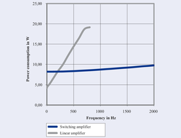
Image: Physik Instrumente (PI)
Standard supply voltage levels
System designers typically work with these supply rails:
- 12 V DC: Common in consumer electronics, robotics, and battery-powered systems. Sufficient for miniature and some small piezo motors. The driver boosts or converts this to the required AC voltage.
- 24 V DC: Standard industrial automation supply. Adequate for many precision-stage motors with appropriate driver design.
- 48 V DC: Used in higher-power industrial systems, telecom, and some automotive applications. Allows direct drive of medium-sized motors with minimal voltage conversion.
- 120/230 V AC mains: High-power piezo motor systems can derive drive voltage directly from rectified mains, but this is uncommon outside laboratory equipment.
The driver must convert the DC supply to the high-frequency AC drive signal at the required voltage. This conversion step determines much of the driver's complexity, size, and efficiency.
Current consumption
Reactive current dominance
The current drawn by a piezo motor is primarily reactive (charging and discharging C₀). The reactive current at frequency f with voltage V across capacitance C₀ is:
I_reactive = 2π × f × C₀ × V
For a motor with C₀ = 10 nF, driven at 40 kHz and 100 V peak:
I_reactive = 2π × 40,000 × 10 × 10⁻⁹ × 100 = 0.25 A peak
The real (active) current, which does mechanical work and accounts for losses, is typically 10 to 50% of the reactive current. Total current is the vector sum of reactive and active components.
Current at different operating points
| Condition | Current (relative) | Notes |
|---|---|---|
| No load, no contact | Low | Only reactive current and dielectric loss |
| Free running (no external load) | Moderate | Reactive plus friction interface losses |
| Loaded (pushing against resistance) | High | Reactive plus mechanical work plus friction losses |
| Stalled (blocked force) | Highest | Reactive plus maximum friction loss; no mechanical output |
At stall, the motor draws maximum current while producing zero mechanical output. All input power is dissipated as heat in the PZT and friction interface. Drive circuits must either tolerate stall current continuously or include current limiting to protect the motor.
Typical current consumption
- Miniature motors (camera AF): 50 to 200 mA peak, 10 to 50 mA RMS
- Small precision-stage motors: 100 to 500 mA peak, 30 to 200 mA RMS
- Medium industrial motors: 200 mA to 1 A peak, 100 to 500 mA RMS
- Large high-force motors: 0.5 to 2 A peak, 200 mA to 1 A RMS
Power factor and efficiency
Power factor
Power factor (PF) for a piezo motor is defined as:
PF = P_real / (V_rms × I_rms)
where P_real is the actual power consumed (mechanical output plus losses). Due to the large reactive current from C₀, power factor is typically:
- 0.05 to 0.15 at light load
- 0.2 to 0.5 at full load
- 0.3 to 0.6 near maximum efficiency point
Low power factor means the drive amplifier must be rated for much higher VA than the motor's actual power consumption. A motor consuming 1 W of real power at PF = 0.1 requires a driver rated for 10 VA.
Power factor correction
Some advanced driver designs incorporate power factor correction, typically by adding an inductor in series or parallel with the motor to partially cancel the reactive current from C₀. A series inductor L tuned so that 2πfL = 1/(2πfC₀) creates a series resonance that cancels the reactive component at the operating frequency. This can improve power factor to 0.7 to 0.9 and significantly reduce the driver's current rating.
The practical limitation: the inductor must be tuned to the operating frequency, which shifts with temperature. A fixed inductor optimized for room-temperature resonance becomes increasingly mismatched as the motor heats up. Adaptive matching networks (using switched capacitor banks or variable inductors) solve this but add complexity.
Overall system efficiency
The overall electrical-to-mechanical efficiency of a piezo motor system includes:
- DC-to-AC conversion efficiency (driver): 70 to 95%, depending on topology.
- Electromechanical coupling efficiency (PZT): 30 to 60%, limited by the coupling coefficient k² and dielectric losses.
- Friction interface efficiency: 50 to 80%, representing the fraction of stator vibration energy converted to useful motion versus frictional heat.
The combined system efficiency is typically 10 to 30%, comparable to small electromagnetic motors but achieved at much lower speeds and higher forces per unit volume. The efficiency is highest at moderate load (40 to 70% of stall force) and drops at both light load and near stall.
Driver topologies
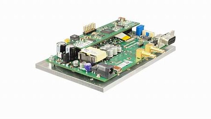
Image: PI E-609 OEM piezo controller module with integrated amplifier, servo controller, and digital interfaces on a compact PCB. Source: PI
Half-bridge
The simplest switching topology: two transistors (MOSFETs or GaN FETs) alternately connect one motor terminal to the supply voltage and ground. Produces a square wave at the motor's resonant frequency. Advantages: simple, low component count, compact. Disadvantages: voltage limited to the supply rail, square-wave drive increases PZT heating.
For a 48 V supply, the half-bridge produces a 48 V peak-to-peak square wave (24 V peak). Suitable for small to medium motors with low voltage requirements.
Full H-bridge
Four transistors configured as a full bridge, driving the motor differentially. Produces a bipolar square wave with peak-to-peak voltage equal to twice the supply voltage. A 48 V supply produces a 96 V peak-to-peak (48 V peak) square wave. This doubles the available voltage compared to a half-bridge.
For two-phase motors, two H-bridges are used, one per phase, with the control logic managing the 90° phase relationship.
Class D amplifier with LC filter
A switching amplifier (half-bridge or H-bridge) followed by an LC low-pass filter that removes harmonics, producing a near-sinusoidal output. Filter design: the LC cutoff frequency is set between the fundamental frequency and the third harmonic (e.g., for a 40 kHz motor, the filter cuts off at 60 to 80 kHz). This topology achieves 85 to 95% driver efficiency with clean sinusoidal output.
The filter components (inductor and capacitor) must handle the full motor current at high frequency, which requires careful selection of core material (ferrite or powdered iron) and capacitor type (film, not electrolytic).
Linear amplifier (Class AB)
A linear amplifier produces a true sine wave with excellent fidelity and no switching noise. Efficiency is low (30 to 50%), and the amplifier must dissipate the difference between supply power and output power as heat. Used in laboratory setups and some precision instruments where EMI and signal purity are paramount. Not practical for battery-powered or high-power applications.
Transformer-coupled designs
A step-up transformer between the driver stage and the motor allows a low-voltage driver to produce high-voltage motor drive signals. A 24 V supply with a 1:5 transformer produces 120 V peak at the motor. Advantages: uses standard low-voltage components, provides galvanic isolation. Disadvantages: transformer size and weight at 20 to 200 kHz, core losses, leakage inductance affects waveform quality.
Piezoelectric transformers (PTs) are an alternative: a piezo element that steps up voltage through mechanical resonance rather than magnetic coupling. PTs are compact and efficient (90 to 95%) but are limited in power handling (typically < 5 W) and must be matched to the motor's frequency.
Integration with third-party controllers
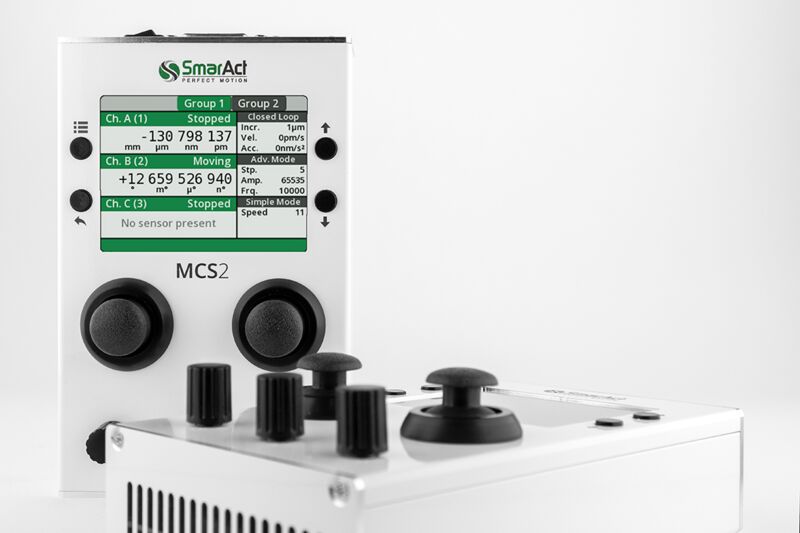
Image: SmarAct MCS2 controller, a multi-channel piezo motor driver with integrated closed-loop positioning, digital display, and manual joystick control. Source: SmarAct
The interface challenge
Most motion controllers in industrial automation are designed for electromagnetic motors: stepper drivers output step/direction pulses; servo drives output PWM to an H-bridge for a brushless DC or AC motor. Piezo motors require fundamentally different drive signals (high-frequency AC at specific voltage, frequency, and phase), creating an integration gap.
Integration architectures
Dedicated piezo driver with analog input. The simplest integration: a standalone piezo driver accepts an analog velocity command (0 to 10 V or ±10 V) and generates the appropriate high-frequency drive signal. The system's motion controller treats it like a voice coil or DC motor, outputting an analog command. The piezo driver handles all resonance tracking and two-phase generation internally.
This architecture works well but adds a separate box (the piezo driver) to the system, with associated cost, space, and wiring.
Dedicated piezo driver with digital interface. Same as above, but the command interface is digital: RS-232, SPI, EtherCAT, or a proprietary protocol. This allows the system controller to set velocity, read position (if the driver includes encoder processing), and monitor motor status. More capable but requires software integration.
Integrated piezo driver on a motion controller card. Some motion controller manufacturers offer plug-in modules that generate piezo drive signals directly. The controller's trajectory generator feeds the piezo module, which handles resonance tracking and power amplification. This provides the tightest integration but limits the user to a specific controller platform.
FPGA-based custom driver. For OEM applications where volume justifies the engineering cost, a custom driver implemented on an FPGA can generate the drive signals with full flexibility. The FPGA implements the DDS (direct digital synthesis) for frequency generation, the PLL for resonance tracking, and the PWM for the power stage. The motion controller communicates with the FPGA over SPI, parallel I/O, or a fieldbus.
Closed-loop position control
Piezo motors are inherently open-loop devices: the relationship between drive signal and velocity is nonlinear and load-dependent. For precision positioning, closed-loop control with an external position sensor (encoder, interferometer, capacitive sensor) is mandatory.
The control loop structure:
- Position controller (PID or more advanced): compares desired and actual position, outputs a velocity command.
- Velocity controller (optional, for scanning applications): compares desired and actual velocity, outputs a drive amplitude command.
- Piezo driver: converts the amplitude command to a high-frequency drive signal at the tracked resonant frequency.
- Motor: converts the drive signal to motion.
- Position sensor: measures actual position and feeds back to the position controller.
The control bandwidth is limited by the motor's mechanical response time (typically 0.5 to 5 ms for ultrasonic motors) and the sensor update rate. Servo bandwidths of 100 to 500 Hz are typical for piezo positioning stages, adequate for most positioning and scanning applications.
Step/direction interface emulation
Some piezo driver manufacturers provide a step/direction interface that makes the piezo motor appear to the controller as a stepper motor. Each step pulse commands a fixed increment of motion (e.g., 100 nm per step). The driver internally generates the appropriate AC drive signal and uses encoder feedback to deliver the commanded step size. This simplifies integration with existing stepper-motor infrastructure but limits performance: the motor cannot achieve its maximum velocity if the step rate is limited by the controller's pulse output frequency.
Battery-powered operation
Why piezo motors suit battery power
Piezo motors have several characteristics that favour battery-powered applications:
- Zero holding current. The self-locking property means no power is consumed while holding position. This is a decisive advantage over electromagnetic motors, which require continuous current to maintain position (or need a brake mechanism).
- Low average power. In intermittent applications, average power consumption can be under 100 mW despite peak power of several watts during motion.
- Compact drive electronics. The driver can be miniaturized to fit within the device envelope.
Voltage conversion challenges
Battery voltages (3.7 V for single Li-ion, 7.4 to 14.8 V for multi-cell packs, 24 to 48 V for power tool and vehicle batteries) are often lower than the motor's required drive voltage. A boost converter or charge pump must step up the voltage, with associated efficiency losses (5 to 15%) and EMI generation.
For low-voltage motors (multi-layer PZT, 12 to 30 V drive), single-cell or dual-cell Li-ion packs can drive the motor through a simple boost converter with > 90% efficiency. For high-voltage motors (100+ V drive), the voltage conversion ratio becomes large (10x to 30x), reducing converter efficiency to 75 to 85% and increasing component stress.
Power budget example
A battery-powered lens positioning system:
- Motor: miniature standing-wave, 20 V peak drive, 50 mA RMS at load
- Motion profile: 5 mm travel in 100 ms, then hold for 10 s
- Motion power: 20 V × 50 mA × 0.3 (PF) = 0.3 W during motion
- Average power: 0.3 W × (0.1 / 10.1) = 3 mW
- Driver quiescent power: 5 mW (microcontroller, PLL, standby circuits)
- Total average power: 8 mW
- Battery: single 18650 Li-ion, 3.7 V, 3000 mAh = 11.1 Wh
- Theoretical runtime at 8 mW average: 11,100 / 8 = 1388 hours = 58 days
In practice, with boost converter losses and other system loads, runtime would be shorter, but the core point stands: piezo motors are extremely battery-friendly for intermittent positioning.
EMI considerations
Sources of EMI
Ultrasonic piezo motor systems generate electromagnetic interference from several sources:
-
Switching transients in the driver. H-bridge and half-bridge topologies produce fast voltage transitions (dV/dt of 1 to 10 V/ns with GaN FETs, 0.1 to 1 V/ns with silicon MOSFETs). These transitions couple into nearby circuits through parasitic capacitance and radiate from wiring and PCB traces.
-
High-frequency motor current. The 20 to 200 kHz motor current flows through cables between the driver and motor. If these cables are not properly shielded or twisted, they act as loop antennas radiating at the drive frequency and its harmonics.
-
Harmonic content. Square-wave drive generates harmonics at 3f, 5f, 7f, etc. For a 40 kHz motor, the third harmonic at 120 kHz and fifth harmonic at 200 kHz fall in frequency bands where radiated EMI regulations are strict.
EMI mitigation
Cable shielding. Use shielded twisted-pair or coaxial cable between the driver and motor. Ground the shield at the driver end (single-point ground) to avoid ground loops.
Output filtering. An LC filter on the driver output reduces harmonic content before it reaches the motor cable. This also improves motor efficiency by reducing PZT dielectric heating from harmonics.
Slew rate control. Reducing the switching speed of the driver transistors (by adding gate resistance or using slower devices) reduces high-frequency EMI at the cost of slightly increased switching losses. A dV/dt of 0.5 V/ns is often an acceptable compromise.
PCB layout. Keep the high-current drive loop (driver output to motor and back) as small as possible. Place decoupling capacitors close to the driver IC. Use ground planes to provide low-impedance return paths.
Spread-spectrum modulation. Some advanced drivers modulate the switching frequency by ±1 to 5% around the resonant frequency, spreading the EMI energy across a wider bandwidth and reducing peak emissions. This technique is borrowed from switch-mode power supply design and is effective for meeting conducted emissions limits.
Regulatory compliance
Piezo motor systems must comply with EMC regulations (FCC Part 15 in the US, CE marking under the EMC Directive in the EU, VCCI in Japan). The 20 to 200 kHz operating frequency falls in the conducted emissions range (150 kHz to 30 MHz for EN 55032), and harmonics extend into the radiated emissions range (30 MHz to 1 GHz).
In practice, well-designed piezo motor drivers meet Class B (residential) emissions limits with basic mitigation measures: shielded cables, output filtering, and proper PCB layout. Class A (industrial) compliance is typically straightforward. The main challenge is conducted emissions on the DC power input, where the switching converter's input current ripple must be filtered.
Practical driver design checklist
For engineers designing or selecting a piezo motor driver, the key specifications to verify:
-
Output voltage range. Must cover the motor's rated voltage with 20% margin for PLL tracking variations. If the motor is rated at 100 V peak, the driver should deliver at least 120 V peak.
-
Output current capacity. Must supply the reactive current at worst-case capacitance and voltage. Calculate I = 2πfC₀V and add 50% margin for load current.
-
Frequency range. Must span the motor's resonant frequency with margin for temperature drift (±3% minimum, ±5% preferred).
-
Frequency resolution. For motors with high Q (> 500), the frequency step size must be small enough to stay within the 3 dB bandwidth. A 40 kHz motor with Q = 1000 has a 40 Hz bandwidth; the frequency resolution should be 5 Hz or better.
-
Phase accuracy (two-phase motors). The phase error between drive channels should be less than 2° for high-performance applications, less than 5° for standard applications.
-
Resonance tracking method. PLL, impedance tracking, or digital scanning. PLL is the most common; verify the lock range and tracking speed match the application's temperature and load transient requirements.
-
Protection features. Overcurrent protection (to survive motor stall), overvoltage protection, and thermal shutdown. Optional: automatic drive reduction at elevated motor temperature.
-
Command interface. Analog (0 to 10 V, ±10 V), digital (SPI, I²C, UART), or fieldbus (EtherCAT, CANopen) as required by the system controller.
-
EMC compliance. Conducted and radiated emissions must meet the target regulatory standard. Request EMC test reports from the driver manufacturer.
-
Efficiency. At the application's typical operating point, not just at peak output. A driver that is 90% efficient at full load but 50% efficient at 10% load will run hot in a low-duty-cycle application if it does not have a sleep mode.
Common pitfalls
Driving a piezo motor with a DC signal. Applying DC to a PZT element does not produce useful motion in an ultrasonic motor. It produces a static deflection, which is used in quasi-static piezo actuators (stack or bender type) but is irrelevant for ultrasonic motors. Worse, sustained DC can cause electrochemical migration in the PZT electrodes, leading to short-circuit failure.
Using an audio amplifier. Audio amplifiers operate at 20 Hz to 20 kHz with 4 to 8 Ω loads. Piezo motors operate at 20 to 200 kHz with highly reactive loads that can exceed the amplifier's stability limits. Some audio amplifiers can be pressed into service for prototype work with 20 to 40 kHz motors, but they are inefficient (driving a capacitive load), may overheat, and provide no resonance tracking.
Ignoring cable capacitance. Long cables between the driver and motor add parasitic capacitance (typically 50 to 100 pF/m for coaxial cable). This capacitance appears in parallel with C₀, increasing reactive current and shifting the electrical resonance. For cable lengths above 1 m, the additional capacitance should be included in the driver's current budget and PLL tuning.
Fixed-frequency drive. As discussed in the thermal behaviour article, fixed-frequency drive is viable only when the motor temperature is tightly controlled (±5 °C). For all other cases, frequency tracking is mandatory.
Overdriving. Increasing the drive voltage above the rated level increases motor force and speed, tempting engineers to push the limits. However, overdriving accelerates PZT fatigue, increases dielectric heating, and can cause mechanical failure of the stator. The rated voltage represents the manufacturer's assessment of the safe long-term operating point; exceeding it by more than 10% without explicit authorization voids the motor's life warranty.
Summary
Driving an ultrasonic piezo motor requires high-frequency AC excitation at a precisely tracked resonant frequency, with voltage levels from 10 V to 200 V peak and currents dominated by reactive power. The driver topology (H-bridge, Class D, linear, transformer-coupled) must match the motor's voltage and current requirements while maintaining signal quality and efficiency. Integration with standard motion controllers is achieved through analog or digital command interfaces, with the piezo driver handling resonance tracking internally. Battery operation is practical for intermittent positioning thanks to the motor's zero holding power, provided the voltage conversion is efficient. EMI management requires shielded cabling, output filtering, and careful PCB layout. Successful piezo motor system design treats the driver electronics as a co-equal partner to the motor, deserving the same level of specification, design, and validation effort.