Fundamentals
Piezo motor specifications explained: what the datasheet doesn't tell you
How to read piezoelectric motor datasheets critically, understand the test conditions behind the numbers, and ask the right questions
Datasheets are marketing documents
Every engineering datasheet serves two masters: technical communication and sales. The numbers on a piezo motor datasheet are not fabricated, but they are presented under conditions chosen to make the motor look as good as possible. If you design a system assuming the headline specifications are achievable simultaneously and under your specific operating conditions, you will be disappointed.
This is not a criticism unique to piezo motor vendors. The same dynamic exists in semiconductor datasheets, battery specifications, and optical component catalogs. But piezo motors have an unusual number of specifications that interact with each other, depend strongly on test conditions, and mean something subtly different from what a newcomer expects. This article explains each major specification, describes the test conditions that flatter (or deflate) the numbers, and provides a framework for extracting the information you actually need for your design.
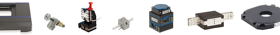
Image: Physik Instrumente (PI)
Stall force vs. working force
What the datasheet says
"Maximum force: 10 N" or "Stall force: 10 N."
What it actually means
Stall force is the maximum force the motor can produce at zero speed. It is the point where the motor is pushing as hard as it can against a load but cannot move. At stall force, the motor is consuming maximum electrical power, all of which converts to heat in the stator and friction interface. The stator temperature rises rapidly.
What the datasheet does not tell you
- You cannot operate at stall force continuously. Most motors will overheat and depole within seconds to minutes at stall. The stall force is a transient specification.
- Working force (continuous force) is typically 20% to 50% of stall force. The motor can sustain this force indefinitely without overheating (see thermal behaviour for temperature limits). Some datasheets list this number; many do not.
- Force depends on speed. The force-speed curve of a piezo motor is roughly (but not exactly) linear: maximum speed at zero force, zero speed at stall force. Your operating point is somewhere on this curve. A motor that produces 10 N at stall might produce only 6 N at half its maximum speed.
- Force depends on preload. The normal force pressing the stator against the slider (preload) directly affects the available lateral force. The optimal preload for maximum force is specific to each motor design. Too little preload reduces the friction coupling and cuts force. Too much preload increases stiction and wear, wastes energy, and can reduce force by mechanically overloading the stator.
- Force depends on drive voltage and frequency. The datasheet probably specifies force at maximum drive voltage at the optimal frequency. Running at lower voltage (for finer speed control) proportionally reduces available force.
What to ask the vendor
- What is the continuous (rated) force at the rated duty cycle?
- Provide the complete force-speed curve at the datasheet drive conditions.
- What preload was used for the force specification?
- How does force degrade over lifetime (friction surface wear)?
No-load speed vs. loaded speed
What the datasheet says
"Maximum speed: 500 mm/s" or "No-load speed: 500 mm/s."
What it actually means
No-load speed is the maximum speed the motor achieves when moving a load so light that friction and inertia within the motor's own mechanism dominate. There is essentially no external force opposing the motion.
What the datasheet does not tell you
- Your application has a load. Under load, speed drops. The force-speed curve is your guide: if your working force is 30% of stall force, your loaded speed is approximately 70% of no-load speed (for a linear force-speed curve). Real curves are often concave, so the actual loaded speed may be lower.
- Speed depends on orientation. A motor moving a stage horizontally at 500 mm/s might manage only 350 mm/s when driving the same stage vertically, because gravity adds a constant force load.
- Speed depends on temperature. As the stator heats up during operation, the resonant frequency shifts, and the drive electronics may not track perfectly. Speed can drop by 5% to 15% over the first few minutes of continuous operation as the system reaches thermal equilibrium.
- Acceleration matters more than top speed for many applications. A motor with 500 mm/s top speed but 2 m/s^2 acceleration takes 250 ms to reach full speed, covering 62.5 mm in the process. If your move distance is 10 mm, you never reach the top speed, and the relevant specification is acceleration (which is force divided by moving mass).
What to ask the vendor
- Provide the force-speed curve for the specific motor variant being quoted.
- What is the acceleration capability with a specified payload mass?
- What is the speed stability (velocity ripple) at a specified speed and load?
Resolution vs. repeatability vs. accuracy
These three terms are often confused, sometimes deliberately, because "resolution" is always the most impressive number. They measure different things.
Resolution
What the datasheet says: "Resolution: < 1 nm" or "Minimum step size: 0.5 nm."
What it actually means: The smallest increment of motion that the motor can produce and the sensor can detect. For a piezo motor, this is typically determined by the stick-slip step size in stepping mode, or the encoder resolution in servo mode.
What the datasheet does not tell you:
- Resolution is a sensor specification as much as a motor specification. A motor with a 1 nm encoder shows 1 nm resolution. The same motor with a 50 nm encoder shows 50 nm resolution. The motor did not change.
- Achieving the specified resolution requires a vibration-isolated environment, temperature stability, and a well-tuned controller. In a typical laboratory environment (not on an isolation table), floor vibrations of 10 to 100 nm are common. Your 1 nm resolution motor will jitter by this amount regardless.
- "Resolution" in open-loop step mode means the motor can make individual steps of that size. It does not mean it will reliably make 1000 consecutive steps of exactly that size. Step size varies due to friction variation, preload, and surface condition.
Repeatability
What the datasheet says: "Bidirectional repeatability: +-50 nm" or "Unidirectional repeatability: +-10 nm."
What it actually means: If you command the motor to the same position repeatedly, repeatability describes how tightly the actual arrival positions cluster. Unidirectional repeatability measures this when approaching from the same direction every time. Bidirectional repeatability measures it when approaching from both directions.
What the datasheet does not tell you:
- Bidirectional repeatability is always worse than unidirectional (because of hysteresis and backlash in the system). Some vendors quote only unidirectional repeatability, which can be 2x to 10x better. Check which one is specified.
- Repeatability is measured over a short time span (minutes to hours). Over days or weeks, thermal drift in the stage, encoder, and mounting structure can exceed the stated repeatability.
- The quoted repeatability was probably measured at one or a few specific positions, under controlled temperature, on a vibration-isolated table. Your repeatability across the full travel range, in a factory environment, will be worse.
Accuracy
What the datasheet says: "Accuracy: +-1 um over 50 mm travel" or "Position accuracy: +-0.5 um."
What it actually means: The maximum deviation between the commanded position and the true position at any point over the full travel range, as verified against a reference standard (typically a laser interferometer).
What the datasheet does not tell you:
- Accuracy is dominated by the encoder, not the motor. A motor with a +-0.5 um accuracy encoder has +-0.5 um accuracy at best, regardless of the motor's own capabilities.
- Accuracy specifications are measured at a reference temperature (usually 20 C). Thermal expansion of the stage, scale, and workpiece degrades accuracy. An aluminum stage has a thermal expansion coefficient of 23 ppm/C. A 100 mm travel aluminum stage changes length by 2.3 um per degree C, which can exceed the stated accuracy with just a 0.5 C temperature change.
- "Accuracy" sometimes means "accuracy after calibration," where a lookup table of correction values is stored in the controller. The raw (uncalibrated) accuracy may be 5x to 10x worse.
- Abbe error (the error caused by measuring position at a point offset from the actual point of interest) is usually not included in the datasheet accuracy. If the encoder scale is 10 mm away from the workpiece, and there is 10 urad of angular error in the stage, the Abbe error is 100 nm, which may dominate the accuracy budget.
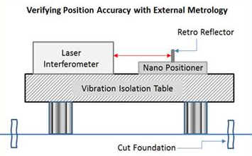
Image: Verifying position accuracy with external laser interferometer metrology. The test conditions (vibration isolation table, temperature-controlled lab) are rarely replicated in real applications. Source: Physik Instrumente (PI)
Putting the three together
A typical piezo-driven linear stage might specify:
- Resolution: 1 nm
- Repeatability (bidirectional): +-50 nm
- Accuracy: +-1 um
Note the three-order-of-magnitude spread. The system can detect 1 nm changes, reliably return to the same point within 50 nm, but the absolute position is only known to +-1 um. These are not contradictory; they measure different aspects of positioning performance.
For most applications, repeatability is the specification that matters most. If you repeatedly position a part at the same location (e.g., for wafer alignment, optical fiber coupling, or pick-and-place), you care about repeatability. Accuracy matters only if you need absolute position knowledge (e.g., for calibrated coordinate measurement).
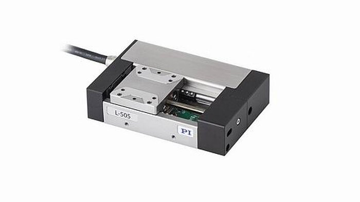
Image: Physik Instrumente (PI)
Lifetime and reliability
What the datasheet says
"Lifetime: > 10,000 hours" or "Lifetime: > 20,000 km of travel."
What it actually means
The motor will still function (produce motion) after the stated distance or time, under the vendor's test conditions.
What the datasheet does not tell you
- "Still functions" is not the same as "meets all specifications." Force, speed, and positional accuracy all degrade over the motor's life as the friction surface wears. A motor may "work" at 20,000 km but produce only 60% of its original force.
- Lifetime depends enormously on operating conditions. Preload, duty cycle, speed, load force, environment (temperature, humidity, particulates), and drive conditions all affect wear rate. The vendor tested under optimized conditions. Your conditions may be more severe.
- The friction surface is the wear item. In most piezo motors, a polymer or ceramic friction pad on the stator contacts the moving surface. This pad wears over time, changing the preload, friction characteristics, and ultimately the motor performance. Some designs allow pad replacement; others do not.
- Wear produces particles. In cleanroom or vacuum applications, the wear debris from the friction interface can be a contamination concern. The rate and composition of particle generation are rarely specified.
What to ask the vendor
- What are the test conditions (preload, duty cycle, speed, load, temperature) for the lifetime specification?
- What is the quantitative performance degradation at end-of-life (e.g., force at 50%, speed at 80%)?
- What is the wear rate (micrometers of material loss per kilometer of travel)?
- Is the friction surface replaceable in the field?
- What particle generation data is available?
Holding force and power-off stability
What the datasheet says
"Holding force: 20 N" or "Power-off holding force: 15 N."
What it actually means
The force required to move the motor when the drive signal is off. This is the static friction between the stator and slider, which is determined by the preload force, friction coefficient, and contact geometry.
Why this matters: Piezo motors hold position with zero power consumption and zero heat generation when stopped. This is a major advantage over electromagnetic motors, which require continuous current (and heat) to hold position against a force. Applications in vacuum, cryogenic, or battery-powered systems particularly benefit from power-off holding.
What the datasheet does not tell you
- Holding force is proportional to preload. If the preload decreases (due to thermal expansion, mechanical relaxation, or wear), holding force decreases proportionally.
- Holding force is a static specification. A dynamic disturbance (vibration, shock) can momentarily overcome static friction and cause the motor to slip. The recovery from such a slip requires the controller to detect the position change and actively correct it.
- In vertical applications, the holding force must exceed the gravitational load on the moving mass. If it does not, the stage will creep downward when power is removed.
Test conditions that flatter specifications
Being aware of common testing practices helps you interpret datasheets more critically:
Short-duration tests. Stall force, maximum speed, and acceleration are often measured in short bursts (seconds) before the motor heats up. Thermal derating is significant; expect 10% to 30% lower performance under continuous operation.
Optimal preload. The vendor tunes the preload for the test being performed. Maximum force tests may use higher preload; maximum speed tests may use lower preload. Your fixed preload in a production stage is a compromise between the two.
Laboratory conditions. Tests on vibration-isolated optical tables, at 20.0 C +- 0.1 C, with ultra-clean friction surfaces. Your factory floor, with its thermal cycling, vibration, and contamination, is less forgiving.
Single-axis isolation. Specifications are measured with the motor driving a single, well-aligned axis. Cross-coupling, misalignment, and off-axis loads in real multi-axis systems degrade performance.
Best-of-N selection. Some vendors test multiple units and publish the best results. The motor you receive may be average, not best.
Freshly manufactured. A new motor with a pristine friction surface performs at its peak. After run-in (initial wear period), some specifications change. After extended use, more specifications degrade. Datasheet values are typically for new or lightly run-in motors.
Electrical specifications and drive requirements
Drive voltage and current
"Drive voltage: 150 Vpp" tells you the peak-to-peak voltage the motor requires. The drive electronics must supply this voltage at the motor's resonant frequency (typically 20 to 200 kHz) with low distortion.
Hidden implications:
- The motor is a capacitive load, not resistive. At 40 kHz with a typical stator capacitance of 5 nF, the reactive current is I = 2 * pi * f * C * V = 2 * 3.14159 * 40000 * 5e-9 * 75 = 94 mA peak. The real power consumption is much lower (only the resistive component), but the amplifier must handle the reactive current.
- Two-phase motors require two drive channels with precise amplitude and 90-degree phase relationship. Phase errors of even a few degrees degrade performance significantly.
- The power amplifier must have bandwidth significantly above the drive frequency to maintain waveform quality at the harmonics.
Power consumption
"Power consumption: 2 W" is the real (active) power, which converts to heat and mechanical work. The apparent power (voltage times current) is much higher due to the reactive component. Your power supply must be rated for the apparent power, not just the real power.
Environmental specifications
Temperature range
"Operating temperature: -20 to +70 C" refers to the ambient temperature range. The stator temperature will be higher than ambient during operation due to self-heating. If the maximum stator temperature approaches the PZT depoling onset (typically 50% to 70% of the Curie temperature for long-term reliability), performance degrades.
At low temperatures, the PZT properties change: d coefficients decrease, Qm increases, and the resonant frequency shifts upward. The drive electronics must accommodate the frequency shift.
Vacuum compatibility
"Vacuum compatible to 10^-6 mbar" means the motor has been tested in vacuum, but the details matter:
- What outgassing rate (TML, CQCM) was measured?
- Does the motor use any lubricants or adhesives that outgas?
- Does the friction interface generate more wear particles in vacuum (common because the oxide layer that normally forms on the friction surface in air is absent)?
- Is the encoder compatible with the vacuum level?
Magnetic cleanliness
"Non-magnetic" or "no magnetic field emissions" is a major selling point for piezo motors. But verify the details:
- Does the encoder have magnetic components? (Magnetic encoders obviously are not non-magnetic. Even some optical encoders use magnetic mounting elements.)
- Are the wiring and connectors non-magnetic?
- What is the residual magnetic field at a specified distance? Some applications (electron microscopy, NMR, MRI) require field levels below 0.5 mT at specific distances.
What to ask the vendor: a checklist
Before specifying a piezo motor for your application, request or determine the following:
- Force-speed curve at the specified preload and drive conditions.
- Continuous (rated) force and speed at the rated duty cycle, not just peak values.
- Test conditions for every specification: preload, temperature, duty cycle, load mass, orientation.
- Encoder specifications if integrated: resolution, accuracy, repeatability, update rate, and whether the accuracy is calibrated or raw.
- Lifetime data with quantitative degradation curves, not just a single number.
- Thermal derating curve: how do force and speed change with stator temperature?
- Frequency tuning range of the drive electronics: how much resonant frequency shift can the driver track?
- Preload mechanism details: is preload adjustable? How stable is it over temperature and lifetime?
- Wear particle data if your application is sensitive to contamination.
- Outgassing data (TML, CQCM) if vacuum operation is required.
- Application engineering support: will the vendor help you tune the controller and optimize the system for your specific use case? This is often the difference between a motor that works and one that sits on the shelf.
Building a realistic performance budget
Rather than taking datasheet values at face value, build a performance budget that accounts for real-world derating:
| Parameter | Datasheet value | Typical derating | Working value |
|---|---|---|---|
| Stall force | 10 N | 0.3x to 0.5x for continuous | 3 to 5 N continuous |
| No-load speed | 500 mm/s | 0.5x to 0.8x under load | 250 to 400 mm/s loaded |
| Resolution | 1 nm | 10x to 100x in real environment | 10 to 100 nm effective |
| Repeatability (bidir.) | +-50 nm | 1x to 3x depending on conditions | +-50 to +-150 nm |
| Accuracy | +-1 um | 2x to 5x including thermal effects | +-2 to +-5 um |
| Lifetime | 20,000 km | 0.3x to 1x depending on conditions | 6,000 to 20,000 km |
These derating factors are conservative estimates for typical industrial applications. Your specific numbers will depend on your conditions, but this approach protects against unpleasant surprises during system integration.
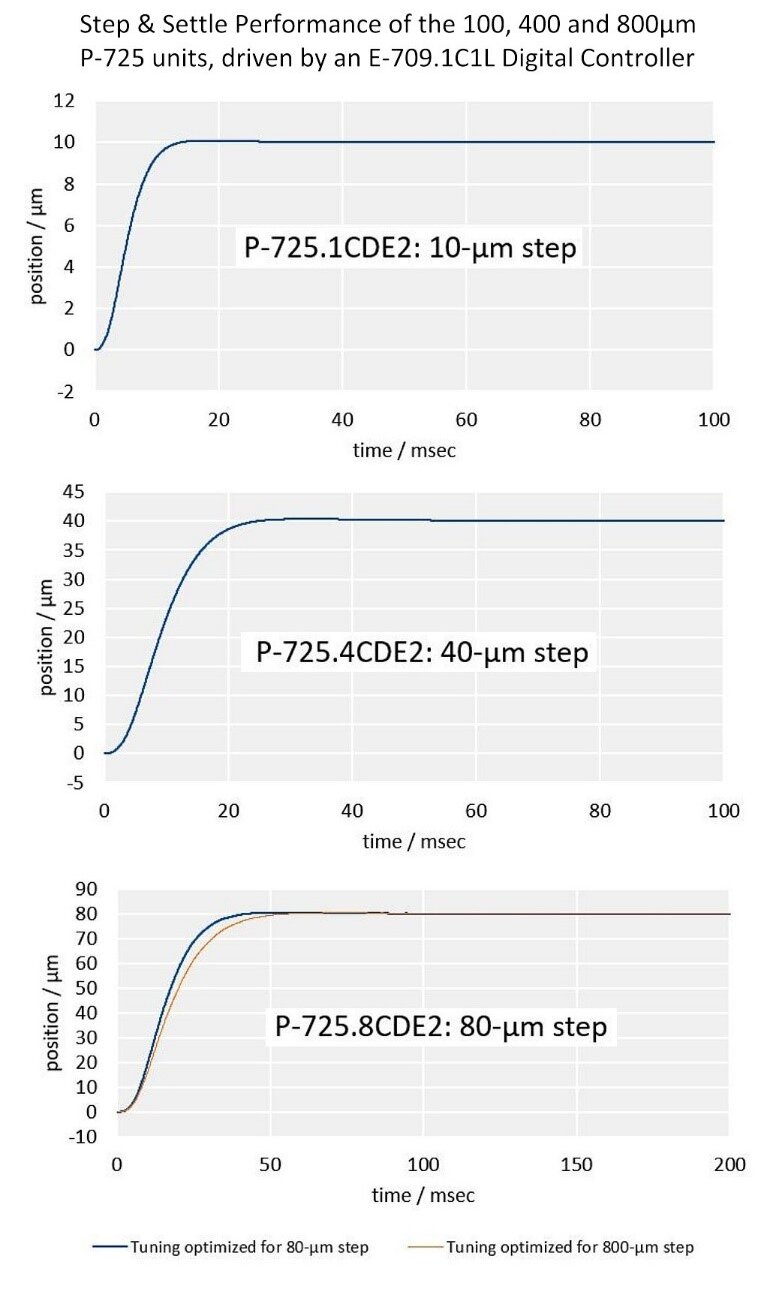
Image: Step and settle performance of the PI P-725 piezo focus motor at three step sizes (10, 40, and 80 um), driven by a digital servo controller. Settling time, not maximum speed, is the governing specification for most short-move applications. Source: Physik Instrumente (PI)
Comparing motors across vendors
When evaluating competing motors, normalize the specifications:
- Compare at the same operating point. A motor rated at 10 N stall force and 500 mm/s no-load speed is not necessarily better than one rated at 8 N and 300 mm/s if the second motor sustains its specifications continuously while the first motor can only achieve them in short bursts.
- Compare force-speed products. The product of maximum force and maximum speed (force * speed = power) gives a rough measure of the motor's total mechanical output capability.
- Compare force density. Force per unit volume or force per unit mass normalizes for motor size. A 5 N motor that fits in a 10 mm cube is more impressive than a 10 N motor that requires a 50 mm cube.
- Compare with your actual operating point identified. Plot your required force and speed on each vendor's force-speed curve. The motor that provides the most margin at your operating point is the better choice, regardless of which has the higher headline specifications.
- Verify specification consistency. If Vendor A claims twice the force of Vendor B for the same motor size and PZT volume, ask how. The physics sets limits; dramatically superior specifications usually indicate different test conditions, not a breakthrough in motor design.
Key Specification Categories
| Parameter | Typical Range | Key Consideration |
|---|---|---|
| Resolution(nm) | 0.5 to 50 | Encoder dependent |
| Repeatability(um) | ±0.1 to 1 | Bidirectional |
| Speed(mm/s) | 10 to 800 | Load dependent |
| Force(N) | 0.5 to 20 | Duty cycle limited |
| Travel(mm) | 5 to 200 | Stage design |
Conclusion
A piezoelectric motor datasheet is a starting point, not a guarantee. The specifications are real but conditional, and the conditions under which they were measured are rarely your conditions. Developing the habit of reading datasheets critically, understanding the physics behind each specification, and asking vendors the right questions will save you integration headaches and redesign cycles. The vendor's application engineers are your best resource; use them early and use them often. The information they share in a 30-minute phone call is often more valuable than the datasheet itself.