基礎原理
ピエゾステージ選定における繰り返し精度と絶対精度
この2つの仕様が本質的に異なる性能を表す理由と、プロセスに適した指標の選び方
ピエゾステージのデータシートには、一見似ているが本質的に異なる性能を示す2つの位置決め仕様が必ず記載されています。繰り返し精度と絶対精度です。この2つを混同することは、精密モーションシステム選定で最もよくある高代価な誤りの一つです。仕様の読み方の記事では、これらの数値がデータシートにどのように記載されるかを解説しています。繰り返し精度50 nmで絶対精度1 µmのステージは、繰り返し精度200 nmで絶対精度200 nmのステージより「劣る」わけではありません。この2つのステージは、まったく異なる用途に適しています。各数値が何を意味し、どのように測定され、どちらがエラーバジェットを支配するかを理解することが、あらゆる精密アプリケーションに適したステージを選定する第一歩です。
Image: Physik Instrumente (PI)
定義:各数値が実際に意味すること
繰り返し精度(一方向繰り返し精度、精密度とも呼ばれる)は、同一方向からの複数回のアプローチにおいて、ステージが同じ指令位置にどれだけ近く戻れるかを定量化します。これはランダムなばらつきの指標です。ステージに同じ方向から10.000 mmへの移動を20回指令した場合、実際の到達位置の標準偏差が繰り返し精度です。データシートでは通常、±2σまたは±3σの値として報告されます。
絶対精度(単に精度、または計量学規格では真度と呼ばれることもある)は、全ストローク範囲にわたって、ステージの報告位置がトレーサブルな基準標準とどれだけ一致するかを定量化します。これは系統誤差の指標です。ステージのエンコーダ(クローズドループ制御で解説)がキャリッジの位置を10.000 mmと示しているのに対し、レーザー干渉計では10.000 47 mmだった場合、その点での絶対精度誤差は470 nmです。
この区別は、計量学における精密度と真度の古典的な概念に直接対応しています。あるステージは高い繰り返し精度(密集したグルーピング)を持ちながら、絶対精度が低い(グループの中心が真値からずれている)ことがあります。逆に、平均的な絶対精度は優れていても、各指令位置周りのばらつきが大きければ繰り返し精度が低いということになります。
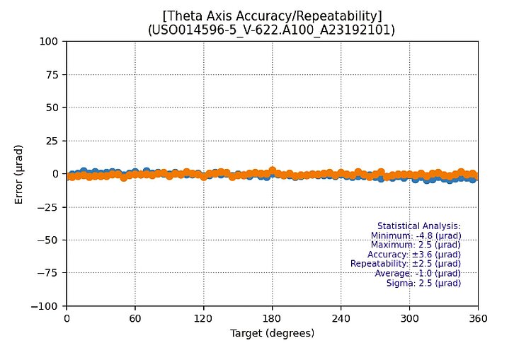
Image: Physik Instrumente (PI)
ISO 230-2と公式な評価フレームワーク
国際規格ISO 230-2は、工作機械の軸の位置決め精度を評価する厳密なフレームワークを規定しており、多くのピエゾステージメーカーがこの方法論を採用しています。この規格では、各目標位置に対して両方向から複数回アプローチを行います。得られたデータから以下が算出されます。
- 一方向繰り返し精度:各目標位置における片方向からのばらつき
- 双方向繰り返し精度:各目標位置における反転誤差を含むばらつき
- 一方向系統位置偏差:各位置における平均誤差(片方向)
- 双方向精度:平均誤差とばらつきの全体的な範囲(両方向)
データシートに単一の「繰り返し精度」値が記載されている場合、通常は全測定目標位置における最悪値の一方向繰り返し精度です。「精度」と記載されている場合は、通常は最大の双方向系統偏差であり、ばらつきが含まれている場合もあります。必ず脚注を確認してください。
エンコーダ品質が繰り返し精度を決定する仕組み
クローズドループ・ピエゾステージにおける繰り返し精度は、フィードバックセンサのノイズフロアと、そのノイズに対するコントローラのサーボ能力に支配されます。ステージ構造(ベアリング、フレクシャ、モータ)が機械的な限界を設定しますが、エンコーダがほぼ常に繰り返し精度の制約要因となります。
リニアエンコーダのアーキテクチャ
ピエゾステージでは3種類のエンコーダが一般的です。
-
光学式インクリメンタルエンコーダ:正弦波信号を内挿処理するタイプです。格子ピッチ4 µmまたは20 µmのガラススケールを走査ヘッドで読み取り、サインおよびコサイン信号を生成します。電子回路がこれらの信号を100倍から4096倍に内挿し、公称分解能1 nmから50 nmを実現します。繰り返し精度のフロアは内挿非線形性(サブディビジョナル誤差、SDE)によって決まり、通常は格子ピッチの1%から3%です。SDEが1%の4 µmピッチスケールの場合、周期誤差成分はピーク・ツー・ピークで約40 nmです。
-
光学式アブソリュートエンコーダ:粗いトラック(または擬似ランダムバイナリコード)を追加することで、電源投入時にリファレンスランなしで直ちに位置を把握できます。微細トラックの性能はインクリメンタルエンコーダと同等です。利点は運用面にあり、原点復帰が不要で、電源断時に位置を失うリスクがありません。
-
静電容量センサ(容量ゲージとも呼ばれる):ターゲットプレートとセンサプローブの間隙を測定し、サブナノメートルのノイズフロアを実現します。短ストロークのフレクシャガイドステージ(ストローク1 mm未満)で一般的です。周期的なスケールがないためサブディビジョナル誤差が存在せず、繰り返し精度は1 nm以下に達することができます。制限は測定範囲で、数ミリメートルを超えると静電容量センサは実用的ではなくなります。
ノイズ、帯域幅、繰り返し精度のフロア
ピエゾステージの典型的な高品質光学エンコーダシステムは、ステージ静止時の電気的ノイズフロアが0.5から2 nm RMSです。しかし、この数値は全体像の一部にすぎません。クローズドループのサーボ帯域幅によって、このノイズのどの程度が実際の位置ジッタに変換されるかが決まります。サーボ帯域幅1 kHzのコントローラは、1 kHz以下のノイズ成分を追従します。つまり、キャリッジは低周波のエンコーダノイズに応答して物理的に動きます。より高周波のノイズは、機械システムの質量と剛性によって減衰されます。
光学エンコーダ(4 µmピッチ、1000倍内挿)を備えた適切に調整されたピエゾステージでは、実用的な繰り返し精度は通常10 nmから100 nmの範囲に収まります。これは内挿品質、サーボチューニング、および熱環境によって変動します。
静電容量センサベースのフレクシャステージでは、0.5 nmから5 nmの繰り返し精度が達成可能ですが、短いストローク範囲(通常500 µm未満)に限られます。
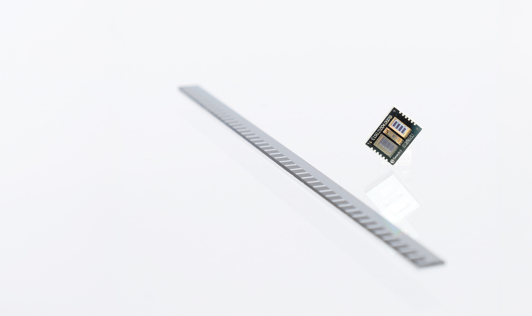
Image: SmarAct GmbH
環境振動と繰り返し精度の測定
データシートの繰り返し精度の仕様は、管理された環境(温度安定化された実験室、防振光学テーブル、低騒音室)で測定されています。実際の設置環境がこれらの条件に一致することはまれです。環境要因が観測される繰り返し精度をどの程度悪化させるかを理解することが、実際のシステム性能を予測する上で重要です。
床振動のカップリング
工場の床に設置されたステージは、人の歩行、空調システム、近接する機械設備からの振動を受けます。軽工業環境では、5 Hzから50 Hzの周波数帯で振幅0.5から5 µmの床振動が一般的です。ステージの防振装置(ある場合)がこれらの外乱を減衰しますが、エンコーダヘッドに伝わる残留振動は、測定される位置ばらつきに直接加算されます。
データシート上の繰り返し精度が20 nm(3σ)のステージを、10 Hzで50 nmの振動がある床に設置すると、観測される繰り返し精度は約√(20² + 50²) = 54 nmに悪化します。これはデータシート値の約3倍です。これはステージの欠陥ではなく、能動的振動キャンセルなしではステージが除去できない環境要因の寄与です。
音響カップリング
クリーンルーム環境では、層流ユニットからの音響ノイズ(通常65から75 dBA)が軽量なステージ構造に結合し、100 Hzから500 Hzの周波数帯で1から10 nmの位置ノイズを発生させることがあります。この影響は、露出面積が大きく構造減衰の低いステージで最も顕著です。
繰り返し精度10 nm以下が必要なアプリケーションでは、ステージを音響シールドで囲むか、低騒音環境に設置する必要があります。あるいは、高帯域幅のクローズドループサーボによって、制御帯域内の音響外乱を能動的に除去することも可能です。
測定中の温度サイクル
名目上安定した環境でも、日周温度変動0.5から2 °Cによってエンコーダスケールとステージ本体が膨張・収縮します。温度サイクルにまたがる期間で繰り返し精度を測定すると、熱ドリフトがばらつきを増大させます。100 mmのアルミニウムステージとガラスエンコーダで0.5 °Cの変化があると、差動膨張は約0.7 µmになります(下記の熱ドリフトのセクションで計算)。これは繰り返し位置測定における緩やかなドリフトとして現れ、測定期間がステージの熱時定数を超えると観測される繰り返し精度を増大させます。
ベストプラクティス:繰り返し精度の測定は、ステージの熱時定数(通常15分から60分)より短い期間で行うか、±0.1 °C以内に制御された環境で行ってください。
絶対精度のキャリブレーション方法
繰り返し精度はエンコーダとサーボループの関数ですが、絶対精度は位置報告チェーン全体がトレーサブルな基準に対してどれだけ正確にキャリブレーションされているかに依存します。
レーザー干渉計によるエラーマッピング
リニアステージのキャリブレーションにおけるゴールドスタンダードは、ヘテロダインレーザー干渉計(Renishaw XL-80やKeysight 5530など)との比較です。手順は以下の通りです。
- 干渉計の光学系を、測定ビームがステージの移動軸と同軸になるように取り付けます。
- ステージに全ストロークにわたる一連の目標位置への移動を指令します(100 mmステージの場合、1 mmまたは0.5 mm間隔が一般的)。
- 各目標位置で、ステージのエンコーダ読み取り値と干渉計の読み取り値の両方を記録します。
- 各点での誤差を算出します:E(x) = encoder_reading(x) − interferometer_reading(x)
- 補正多項式を当てはめるか、誤差のルックアップテーブル(LUT)を格納します。
この補正はコントローラによってリアルタイムに適用されます。ユーザーが位置Xを指令すると、コントローラは実際にはX + correction(X)に駆動します。このプロセスはエラーマッピングまたはキャリブレーションと呼ばれます。
20 °Cでの単一パスキャリブレーションにより、良質なステージの系統精度誤差を数マイクロメートルから100 mmストロークで100から300 nmまで低減できます。キャリブレーション後の残留誤差は以下の要因で制限されます。
- 内挿非線形性(SDE):各格子ピッチで繰り返される
- キャリブレーション時と測定時の温度差による熱膨張
- キャリブレーションで捕捉されなかった機械的ヒステリシスまたは反転誤差
- 干渉計ビームがステージ軸と完全に整列していない場合のコサイン誤差
高次キャリブレーション
最高の絶対精度(数十ミリメートルのストロークで100 nm以下)が求められるアプリケーションでは、より精巧なキャリブレーション戦略が用いられます。
- 双方向キャリブレーション:正方向と負方向のアプローチに対してそれぞれ別個のエラーマップを作成し、コントローラが移動方向に応じて適切なマップを選択します。
- 温度補償キャリブレーション:ステージ本体に温度センサを埋め込み、熱補正モデルを適用します。熱膨張係数(CTE)が23 µm/(m·K)のアルミニウム製ステージでは、1 °Cの温度変化で100 mmのストロークに対して2.3 µmの膨張が生じます。
- 周期誤差補正:干渉計を用いてサブマイクロメートルの微細な位置刻みでエンコーダのサブディビジョナル誤差をマッピングし、周期的な補正を適用します。
熱ドリフト:隠れた精度の敵
熱的影響は、多くの実際の設置環境における絶対精度誤差の最大の単一要因です。20.0 °Cで実施されたキャリブレーションは、その温度でのみ有効です。実際には、ステージ本体、エンコーダスケール、およびワークピースのすべてが温度変化に伴って膨張・収縮します。
熱ドリフトの定量化
150 mmストロークのアルミニウムステージにガラスエンコーダスケールを搭載した例を考えます。アルミニウムのCTEは約23 µm/(m·K)、ガラス(ソーダライム)のCTEは約9 µm/(m·K)です。ステージ本体がキャリブレーション温度に対して0.5 °C上昇した場合を計算します。
- ステージ本体の膨張:150 mm × 23 × 10⁻⁶ /K × 0.5 K = 1.725 µm
- ガラススケールの膨張:150 mm × 9 × 10⁻⁶ /K × 0.5 K = 0.675 µm
- 差動膨張(誤差):1.725 − 0.675 = 1.05 µm
この1.05 µmの誤差は、スケールの固定点からの距離に比例して線形に増大する位置依存の精度オフセットとして現れます。サブマイクロメートルの絶対精度を要求するアプリケーションでは、この値は重大です。
緩和策
- 低CTEスケール材料:Zerodur(CTE ≈ 0.05 µm/(m·K))やInvarスケール基板を使用すると、スケールの熱感度を桁違いに低減できます。一部のメーカーは最高精度ステージにZerodurスケールオプションを提供しています。
- 温度管理された環境:半導体ファブや計測ラボでは通常、温度を±0.1 °C以内に保持し、熱ドリフトを数十ナノメートルに抑えています。
- リアルタイム温度補償:ステージ本体の温度センサと既知のCTE値を組み合わせることで、コントローラが補正を適用できます。これは緩やかで単調な温度ドリフトには有効ですが、急速な過渡変動やステージ全体の温度勾配を補償することはできません。
- 対称的な熱設計:ステージ本体とスケールに整合したCTEの材料を使用するか、熱膨張が測定軸に対して対称になるように設計して相殺させます。
何がより重要か:繰り返し精度か絶対精度か
その答えは、アプリケーションによって完全に異なります。以下に実用的なフレームワークを示します。
繰り返し精度が支配的なアプリケーション
同じ位置セットに何度も戻ることが求められ、その位置の絶対的な場所よりも到達の一貫性が重視されるアプリケーションです。例を挙げます。
- 半導体ウェーハ検査:ステージは同じダイサイトに繰り返しアクセスします。各アクセスが同じ場所の±30 nm以内に着地すれば、各サイトの「真の」位置が名目座標から500 nmずれていても、検査画像は正しくオーバーレイされます。
- 光ファイバアライメント:ピーク結合が見つかった後、外乱を受けた後にもステージはその位置に確実に戻らなければなりません。座標系に対する絶対位置は無関係であり、位置再現性がすべてです。
- 繰り返しディスペンスパターン:マイクロディスペンスシステムが各基板上の同じ相対位置に材料を堆積する場合、繰り返し精度がパターンの忠実度を決定します。
これらのアプリケーションでは、エンコーダ品質(低ノイズ、低SDE)、サーボ剛性、およびエンコーダ取り付けの熱安定性を優先してください。外部基準に対するキャリブレーションは不要な場合があります。
絶対精度が支配的なアプリケーション
ステージ外部に定義された座標系と位置を一致させる必要があるアプリケーションです。例を挙げます。
- フォトマスク描画:パターンの形状は、設計データベースの座標と厳密な許容差以内(多くの場合50 nm以下)で配置する必要があります。ステージは絶対的な位置を把握している必要があり、単に同じ場所に戻れるだけでは不十分です。
- マルチツール座標転送:ワークピースを一つのステージで測定し、別のステージで加工する場合、座標系が一致している必要があります。これには、共有基準に対する優れた絶対精度が両ステージに求められます。
- 計測機器:形状位置を報告する表面プロファイラは、キャリブレーションされた絶対精度を持つ必要があります。そうでなければ、報告される表面形状の座標に系統的な誤りが生じます。
これらのアプリケーションでは、高品質なキャリブレーション(双方向、温度補償が望ましい)に投資し、熱ドリフトが小さく高品質なエンコーダスケールを備えたステージを選定してください。
両方が必要なアプリケーション
繰り返し精度と絶対精度の両方が厳しく求められるアプリケーションもあります。半導体リソグラフィ(ウェーハステッパ)がその典型例です。ステージは各露光フィールドをウェーハ上の正しい絶対位置に配置し(精度)、連続する露光レイヤーをナノメートルレベルの一貫性でオーバーレイする(繰り返し精度)必要があります。これらのシステムでは、レーザー干渉計フィードバック(エンコーダスケールではなく)、能動的温度制御、および高度なエラーマッピングを使用して、両方の指標で一桁ナノメートルの性能を同時に実現していますが、そのコストは非常に高額です。
設計例1:ウェーハ検査ツール用ステージの選定
要件:
- ストローク:200 mm × 200 mm(XY)
- ステージはウェーハあたり500個のダイ位置に繰り返しアクセスし、50倍対物レンズ(視野 ≈ 250 µm)で各サイトを撮像
- 繰り返しアクセス間のオーバーレイ許容差:±100 nm
- 絶対位置許容差(ダイと座標系の関係):±5 µm(緩い。ビジョンシステムがローカルアライメントを実行)
分析:
重要な仕様は繰り返し精度であり、絶対精度ではありません。ビジョンシステムのローカルアライメントが数マイクロメートルの絶対誤差を吸収できますが、ステージが±100 nm以内に戻れなければ、連続パスの検査画像が正しくレジストレーションされません。
選定すべきステージの仕様:
- 一方向繰り返し精度 ≤ ±50 nm(100 nm要件に対するマージンの確保)
- SDEが40 nm(ピーク・ツー・ピーク)以下の光学リニアエンコーダ
- 動的整定時に繰り返し精度を維持するため、サーボ帯域幅 ≥ 500 Hz
絶対精度の仕様は緩和できます。繰り返し精度が目標を満たしていれば、絶対精度±2 µm(未校正)のステージで十分です。
コストへの影響: このステージには高価なレーザー干渉計キャリブレーションやZerodurエンコーダスケールは不要です。標準的なキャリブレーションを施した良質な光学エンコーダステージで十分です。
設計例2:フォトマスク計測システム用ステージの選定
要件:
- ストローク:150 mm × 150 mm
- 測定位置はマスク設計データベースにより絶対座標系で定義される
- 位置精度要件:全ストロークで±100 nm
- 繰り返し精度要件:±50 nm(複数回測定の平均化用)
分析:
両方の仕様が厳格です。150 mmストロークにわたる±100 nmの絶対精度要件は、熱ドリフトだけでエラーバジェット全体を消費し得ることを意味します(前述の0.5 °Cあたり1.05 µmのドリフトを想起してください)。
選定すべきステージの仕様:
- レーザー干渉計フィードバック(エンコーダスケールではない)。SDEおよびスケールの熱膨張を排除
- 温度管理された環境(±0.1 °C以内)
- トレーサブル基準に対する双方向エラーマッピング
- 低CTEのステージ本体材料(花崗岩またはInvarベース)
- エアベアリングガイドウェイ(摩擦に起因するヒステリシスの排除)
レーザー干渉計が実用的でない場合は、以下の仕様のステージを選定します。
- Zerodurエンコーダスケール(CTE < 0.1 µm/(m·K))
- 動作温度での双方向キャリブレーション
- SDEに対する周期誤差補正
- 温度センサとリアルタイム温度補償
コストへの影響: このシステムのコストは、設計例1の検査ステージの5倍から20倍になります。精度要件がコストを支配します。
設計例3:繰り返し精度のエラーバジェット内訳
以下の仕様のステージを考えます。
- エンコーダ:光学式、4 µmピッチ、4096倍内挿(公称分解能 ≈ 1 nm)
- SDE:±20 nm(ピーク・ツー・ピーク周期誤差)
- エンコーダ電気ノイズ:1 nm RMS
- サーボ帯域幅:800 Hz
繰り返し精度のエラーバジェット:
| 誤差源 | 寄与(1σ) | 備考 |
|---|---|---|
| エンコーダノイズ(電気的) | 1.0 nm | 直接測定 |
| SDE(周期的、多数の位置に対してランダムとして扱う) | ~5.7 nm | ≈ 20 nm p-p / (2√3) 一様分布の場合 |
| サーボ追従誤差(静止時) | 0.5 nm | 適切に調整された低外乱条件 |
| 熱によるエンコーダドリフト(短期、±0.01 °C) | 0.56 nm | Alステージとガラススケールの差動膨張:4 mm × (23−9) × 10⁻⁶/K × 0.01 K |
| ベアリング摩擦ヒステリシス | 2.0 nm | クロスローラベアリングの典型値 |
| RSS合計(1σ) | ~6.1 nm | |
| 繰り返し精度(±3σ) | ±18 nm |
このバジェットは、光学エンコーダのSDEが最も大きな寄与要因であることを示しています。より高品質な内挿システムにアップグレードしてSDEを±20 nmから±5 nmに低減すると、繰り返し精度は約±10 nm(3σ)に改善されます。
反転誤差(双方向繰り返し精度)
上記の議論は一方向繰り返し精度、つまりステージが常に同じ方向から目標にアプローチする場合に焦点を当てています。実際には、多くのアプリケーションで双方向の位置決めが必要です。ステージは任意の順序で目標に移動し、正方向からアプローチすることもあれば負方向からアプローチすることもあります。
方向反転によって生じる追加誤差を反転誤差(バックラッシュとも呼ばれますが、ギアバックラッシュのないピエゾステージにはこの用語は不適切)と呼びます。摩擦駆動ピエゾステージでは、反転誤差は以下の要因から生じます。
- 摩擦接触のプレトラベル:駆動方向が反転すると、ロータは静止摩擦と接触部の弾性コンプライアンスを克服する必要があり、ステータの動きがキャリッジの動きに変換される前に不感帯が生じます。この不感帯は通常10から100 nmです。
- ベアリングプリロードの非対称性:クロスローラベアリングやボールベアリングは、荷重の方向によって復元力にわずかな非対称性があります。
- コントローラのオーバーシュート:サーボループが積極的にチューニングされている場合、アプローチの動特性が方向によって異なります。
双方向繰り返し精度は一方向繰り返し精度よりも常に悪くなります。典型的な値として、一方向繰り返し精度が±20 nmの場合、双方向繰り返し精度は±40から±80 nmになることがあります。これは、ピックアンドプレースシステムのように任意の方向から目標にアプローチするアプリケーションにとって重要な仕様です。
アッベ誤差:測定の幾何学
絶対精度に対する最も見落とされがちな寄与因子の一つがアッベ誤差です。Ernst Abbeにちなんで名付けられたアッベ誤差は、測定軸が対象軸と一致しない場合に生じます。エンコーダがステージ上のある位置で位置を測定し、ワークピースやツールが別の位置(エンコーダから距離dだけオフセット)にある場合、ステージキャリッジの角度誤差(ピッチまたはヨー)が、対象点での並進誤差として拡大されます。
アッベ誤差は以下のように計算されます。
e_Abbe = d × sin(θ) ≈ d × θ(小角近似)
ここでdはアッベオフセット(測定軸と機能軸の間の垂直距離)、θはキャリッジの角度誤差(ラジアン)です。
影響の定量化
エンコーダスケールがワークピース表面の15 mm下方に取り付けられたステージを考えます。キャリッジのピッチ誤差が5 µrad(クロスローラベアリングステージの典型値)の場合、ワークピースにおけるアッベ誤差は以下の通りです。
e_Abbe = 15 mm × 5 × 10⁻⁶ = 0.075 µm = 75 nm
絶対精度±100 nmと規定されたステージでは、この単一の寄与因子がバジェットの75%を消費します。さらに問題なのは、ピッチ誤差は通常位置によって変化する(ベアリングの真直度の関数)ため、アッベ誤差は位置依存の精度オフセットとして現れ、角度誤差も測定して補正しない限り単純なキャリブレーションでは除去できないことです。
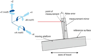
Image: Physik Instrumente (PI)
アッベ誤差の最小化
アッベ誤差を低減する3つのアプローチがあります。
-
アッベオフセットの低減。 エンコーダを機能軸にできるだけ近くに取り付けます。顕微鏡の場合、焦点面の高さにエンコーダを配置することを意味します。機械加工の場合は、工具先端で測定することを意味します。
-
角度誤差の低減。 高品質なベアリングを使用します(エアベアリングのピッチ誤差は100 mmあたり0.5から2 µradであるのに対し、クロスローラベアリングは5から20 µradです)。
-
角度誤差の測定と補正。 デュアルエンコーダ構成またはオートコリメータを使用してピッチとヨーをリアルタイムに測定し、アッベ誤差を計算して差し引きます。これはサブ50 nmの精度要件を持つ計測ステージでは一般的です。
超音波摩擦駆動モータを使用するピエゾステージでは、モータとベアリングの相互作用が角度誤差に影響します。ピエゾモータのプリロード力はキャリッジの特定の点に加わり、駆動状態に応じてピッチ角が変化するモーメントを発生させます。このモータ誘起の角度誤差は通常0.5から2 µradであり、一貫している(繰り返し可能な)ため、キャリブレーションによって除去できます。
長期安定性と短期繰り返し精度
データシートの繰り返し精度は管理された環境下で数分から数時間かけて測定されます。実際のアプリケーションは数日、数ヶ月、あるいは数年にわたって稼働します。長期間にわたって位置キャリブレーションを維持するステージの能力(長期安定性)は、短期繰り返し精度とは別の仕様であり、データシートに記載されることはまれです。
長期ドリフトの原因
エンコーダ位置と真の位置の関係が時間とともに変化する要因はいくつかあります。
-
エンコーダスケールの緩和。 ガラスおよびセラミックエンコーダスケールは接着剤でステージ本体に固定されています。数ヶ月にわたって、接着剤の応力緩和によりスケールがステージ本体に対して10から100 nmシフトすることがあります。スケール自体は正確に読み取れますが、装置の座標系との関係が変化します。
-
ベアリング摩耗。 クロスローラベアリングやボールベアリングは摩耗し、ベースに対するキャリッジの幾何学的な関係が徐々に変化します。10,000 kmの走行距離(高スループット検査ツールでは数ヶ月で蓄積)の後、ベアリングのプリロード、真直度、および角度誤差はキャリブレーション時の状態から測定可能な差異を示すことがあります。
-
温度サイクルの影響。 ステージ構造の繰り返し加熱・冷却は、ボルト接合部や接着接合部のクリープを引き起こします。数百回の温度サイクルにわたって、ステージの形状が50から500 nmシフトすることがあります。
-
PZTのエージング(ピエゾ駆動ステージの場合)。 PZTセラミクスの熱挙動には、モータの力出力を徐々に変化させ、ひいては摩擦駆動ステージの位置キャリブレーションに間接的に影響する時間依存のエージングが含まれます。
再キャリブレーション間隔
500 nm以下の絶対精度を要求するアプリケーションでは、基準標準(レーザー干渉計またはキャリブレーション済みアーティファクト)に対する定期的な再キャリブレーションが必要です。一般的な再キャリブレーション間隔は以下の通りです。
| アプリケーション | 精度要件 | 一般的な再キャリブレーション間隔 |
|---|---|---|
| 半導体計測 | < 100 nm | 毎日から毎週 |
| フォトマスク描画 | < 50 nm | 8から24時間ごと |
| 光学検査 | < 500 nm | 月次 |
| 一般精密組立 | < 2 µm | 年次 |
自動セルフキャリブレーションルーチン(ステージが各シフトやロットの開始時に固定基準アーティファクトを測定)により、オペレータの介入なしに精度を維持できます。このアプローチは半導体ツールでは標準的であり、他の高精度産業でも採用が広がっています。
多軸誤差の相互作用
実際のステージには6自由度があります。X, Y, Zの並進と、各軸周りの回転(ロール、ピッチ、ヨー)です。位置決め精度と繰り返し精度のデータシート仕様は制御軸のみを指しますが、残りの5軸の誤差が対象点での達成精度に影響します。
クロストークと寄生運動
単軸ステージがXに移動する際、YおよびZの寄生運動(真直度誤差)と寄生回転(ロール、ピッチ、ヨー)も発生します。これらの寄生運動はベアリングの不完全さ、ガイドレールの真直度、およびモータ発生のモーメントに起因します。
100 mmストロークの典型的なクロスローラベアリングステージの場合:
| 誤差の種類 | 典型的な大きさ |
|---|---|
| 真直度(Xストロークに対するYの偏差) | 0.5から5 µm |
| 平面度(Xストロークに対するZの偏差) | 0.5から5 µm |
| ピッチ | 5から50 µrad |
| ヨー | 2から20 µrad |
| ロール | 2から20 µrad |
100 mmストロークのエアベアリングステージの場合:
| 誤差の種類 | 典型的な大きさ |
|---|---|
| 真直度 | 0.05から0.5 µm |
| 平面度 | 0.05から0.5 µm |
| ピッチ | 0.5から5 µrad |
| ヨー | 0.2から2 µrad |
| ロール | 0.2から2 µrad |
XYステージの積層誤差
2つの単軸ステージを重ねてXYシステムを構成すると、誤差が複合します。上部ステージ(ワークピースを搭載)は下部ステージの全ての幾何誤差を受け継ぎ、ステージ間のアッベオフセットによって増幅されます。クロスローラベアリングステージで構成された200 mm XYステージは、未校正で通常2から10 µmのXY面内精度を達成します。各軸21点のキャリブレーションによる完全なエラーマッピング後、0.5から2 µmに改善されます。
モノリシックXYステージ(両軸が共通のベースとガイドシステムを共有)は一部の積層誤差を排除し、積層構成よりも通常2倍から5倍優れた面内精度を達成します。エアベアリングXYステージは最高の性能を実現し、キャリブレーション後0.1から1 µmの面内精度を達成します。
データシート評価の実践的アドバイス
データシートを評価する際には、以下のガイドラインを念頭に置いてください。
-
繰り返し精度の測定方法を確認してください。 一方向か双方向か。何サイクルか。熱環境はどうだったか。温度管理された実験室での5サイクルから報告された数値は、工場環境で数千サイクルにわたって達成される値よりも楽観的です。
-
「精度」に何が含まれるかを確認してください。 系統偏差のみか、繰り返し精度のばらつきも含むか(ISO 230-2による双方向精度)。後者がより誠実な数値です。
-
キャリブレーション条件を確認してください。 精度仕様が20.0 °Cでのレーザー干渉計キャリブレーションを前提としている場合、その精度はその条件下でのみ有効です。未校正精度を尋ねてください。これにより、ステージがソフトウェア補正にどの程度依存しているか、機械的精度がどの程度かが分かります。
-
完全な精度プロットを要求してください。 単一の「精度」値(例:100 mmあたり±0.5 µm)は、誤差曲線の形状を隠しています。滑らかでゆっくり変化する誤差のステージもあれば、エンコーダ内挿に起因する鋭い高周波誤差があり、補正が困難で残留精度誤差として再現されるステージもあります。
-
アプリケーションの熱環境を考慮してください。 プロセスが発熱する場合(レーザー加工、高速走査の摩擦)、ステージの実使用精度は安定した実験室で測定されたデータシートの仕様よりも悪化します。
-
双方向の考慮が重要です。 アプリケーションが双方向位置決めを必要とする場合、一方向繰り返し精度の仕様をシステム性能の代表値として受け入れてはなりません。
まとめ
繰り返し精度と絶対精度は補完的な仕様であり、互換性のあるものではありません。繰り返し精度はばらつきを、絶対精度は系統的なオフセットを記述します。エンコーダが繰り返し精度を支配し、キャリブレーションと熱管理が絶対精度を支配します。ステージを選定する前に、アプリケーションが実際に必要とする仕様を見極め、それに応じて予算を配分してください。精度が過剰でも繰り返し精度が適正なステージは、その逆よりもはるかに高コストになりますが、プロセスに対するメリットはありません。