Fundamentals
Payload mounting and centre of gravity offset: moment loading effects on stage life and accuracy
How off-centre payloads generate moment loads that degrade bearing life, increase positioning error, and limit dynamic performance
A precision piezo stage is designed, tested, and specified with a centred payload. The datasheet numbers for accuracy, repeatability, and load capacity assume the payload's centre of gravity (CG) lies on the stage's geometric centre, aligned with the bearing system's designed load path. In practice, payloads are almost never centred. An optical assembly with a lens tube extending 80 mm above and 30 mm to the side of the stage's mounting surface generates moment loads that the bearing system must absorb. These moments reduce bearing life, degrade positioning accuracy, and limit the stage's achievable acceleration. For multi-axis configurations, the compounding effect of CG offsets across stacked axes is even more critical. Understanding and managing CG offset is essential for getting datasheet performance from a real installation. The specifications explained article covers how these datasheet numbers are measured.
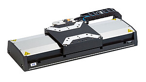
Image: Physik Instrumente (PI)
Centre of gravity and moment loads: the basics
A payload mounted on a stage exerts two categories of mechanical load:
-
Axial (normal) force: the weight of the payload, acting downward through the CG. This is the load that appears on the datasheet as the stage's load capacity.
-
Moment loads: if the CG is offset from the bearing system's centre of support, the gravitational force generates torques (moments) about the bearing axes. Additionally, when the stage accelerates, the inertial force of the payload (F = m × a) acts through the CG and generates additional moments if the CG is offset from the drive force axis.
A moment is defined as force multiplied by distance: M = F × d, where d is the perpendicular distance from the force's line of action to the axis of rotation (or the bearing support point).
Three moment axes
For a linear stage moving in the X direction with the vertical axis as Z:
- Pitch moment (M_y): rotation about the Y axis, caused by a CG offset in the X direction (along the travel axis) or in the Z direction (height above the stage). This is the most common and most damaging moment in linear stage applications.
- Roll moment (M_x): rotation about the X axis (the travel axis), caused by a CG offset in the Y direction (lateral) or the Z direction.
- Yaw moment (M_z): rotation about the Z axis, caused by a CG offset in both X and Y simultaneously, or by lateral forces on the payload.
During static conditions (stage not moving), only gravitational moments exist. During acceleration, inertial moments add to or subtract from the gravitational moments depending on the direction of acceleration.
How offset CG affects positioning accuracy
A payload with its CG offset from the stage's ideal support point introduces several accuracy-degrading effects.
1. Static deflection of the bearing system
Cross-roller bearings, ball bearings, and recirculating guides have finite stiffness against moment loads. When a moment is applied, the carriage tilts slightly. This tilt, combined with the height of the payload above the bearing, produces a lateral position error at the payload (Abbe error).
Example: a cross-roller bearing stage has a pitch stiffness of 200 N·m/mrad. A 5 kg payload with its CG 60 mm above the stage surface and 20 mm forward of the stage centre generates a static pitch moment of:
M_pitch = m × g × d_x = 5 × 9.81 × 0.020 = 0.981 N·m
The resulting pitch tilt is:
θ = M / K_pitch = 0.981 / 200 = 4.9 µrad
At the payload CG height of 60 mm above the bearings, this tilt produces a lateral displacement of:
Δx = θ × h = 4.9 × 10⁻⁶ × 60 mm = 0.29 µm ≈ 290 nm
This 290 nm error is static and constant (as long as the stage is not accelerating), so it can be calibrated out. The problem arises when the moment load changes during operation, as described next.
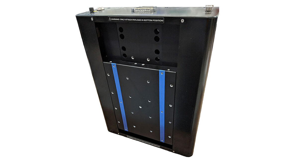
Image: Physik Instrumente (PI)
2. Position-dependent moment variation
In many real installations, the effective CG offset changes with stage position. Consider a payload with a cable bundle attached: as the stage moves, the cable configuration changes, shifting the effective CG. Or consider a payload on a stacked XY stage: as the lower axis moves, the upper axis (and its payload) translates relative to the lower stage's bearings, changing the moment arm.
This position-dependent moment produces a position-dependent tilt, which appears as a systematic accuracy error that varies across the travel range. If the CG offset varies by ±5 mm over the travel (due to cable drag or payload geometry), the pitch moment varies by ±5 × 5 × 9.81 × 10⁻³ = ±0.245 N·m, producing a tilt variation of ±1.2 µrad and a payload position variation of ±73 nm (at 60 mm height). This error is repeatable and can be calibrated, but only if the cable configuration and payload geometry are fixed.
3. Dynamic tilt during acceleration
When the stage accelerates, the inertial force F = m × a acts through the payload's CG. If the CG is above the drive force axis (which it almost always is), a pitch moment is generated:
M_pitch_dynamic = m × a × h_CG
where h_CG is the height of the CG above the drive force axis.
Example: the same 5 kg payload, with CG 60 mm above the drive axis, on a stage accelerating at 5 m/s² (≈ 0.5 g):
M_pitch_dynamic = 5 × 5 × 0.060 = 1.5 N·m
The dynamic pitch tilt is:
θ_dynamic = 1.5 / 200 = 7.5 µrad
This tilt changes the payload's X position by:
Δx_dynamic = 7.5 × 10⁻⁶ × 60 = 0.45 µm = 450 nm
This 450 nm error appears during acceleration and disappears when the stage reaches constant velocity. In a point-to-point application, it extends the settling time because the payload position oscillates as the tilt rings down after the acceleration phase ends. The settling time to achieve sub-100-nm position error may increase by 50% to 200% compared to a centred payload.
4. Bearing compliance asymmetry
Most bearing systems have different stiffness values in different directions and for different load types. A cross-roller bearing stage might have:
- Vertical (Z) stiffness: 500 N/µm
- Lateral (Y) stiffness: 300 N/µm
- Pitch stiffness: 200 N·m/mrad
- Roll stiffness: 150 N·m/mrad
- Yaw stiffness: 100 N·m/mrad
An off-centre CG loads the bearing in its weakest moment axes, amplifying the effect compared to what the vertical load capacity (the strongest axis) might suggest. A stage rated for 20 kg vertical load may only tolerate 2 N·m of pitch moment before accuracy degrades beyond specification.
Moment load effects on bearing life
Beyond accuracy, moment loads directly affect the service life of the bearing system.
Cross-roller and ball bearing life
Rolling-element bearings (cross-roller, ball recirculating) have a rated life based on the equivalent dynamic load. The standard life calculation (ISO 281) uses the relationship:
L_10 = (C / P)^p × 10⁶ revolutions
where C is the basic dynamic load rating, P is the equivalent dynamic load, and p = 3 for ball bearings (10/3 for roller bearings).
Moment loads increase the equivalent dynamic load. For a cross-roller bearing pair, a moment load M increases the maximum ball load from the nominal (gravity-only) value. The equivalent load becomes:
P_eq = F_axial + K_m × M / d_bearing
where K_m is a factor depending on the bearing geometry (typically 2 to 4) and d_bearing is the bearing spacing or diameter.
Example: a stage with a cross-roller bearing rated for C = 5000 N is carrying a 3 kg payload (F = 29.4 N). Without moment loading, P_eq ≈ 30 N, and the bearing life is astronomically long (not the limiting factor).
Adding a 2 N·m moment load with K_m = 3 and d_bearing = 40 mm:
P_eq = 30 + 3 × 2 / 0.040 = 30 + 150 = 180 N
The bearing life ratio changes from (5000/30)^3 ≈ 4.6 × 10⁶ to (5000/180)^3 ≈ 21,400. The life is reduced by a factor of 215. While the absolute life may still be acceptable (millions of cycles for a piezo stage operating at moderate speeds), the reduction is dramatic and not obvious from the datasheet load rating.
Air bearing implications
Air bearings do not have the same life limitation (no rolling contact, no wear), but they do have a maximum moment capacity. Exceeding this capacity causes the air film to collapse on one edge of the bearing pad, resulting in contact between the bearing surface and the guide, which causes immediate damage. Air bearing moment capacity is typically specified as a maximum allowable moment (e.g., 2.5 N·m), and exceeding it is a hard failure mode rather than a gradual degradation.
Flexure bearing implications
Flexure-guided stages (common in short-travel piezo stages) tolerate moment loads differently. The flexure deflects under the moment load, and as long as the stress remains within the elastic limit, there is no life reduction. However, the deflection alters the stage's geometry, shifting the pivot point and introducing parasitic motion (unwanted lateral or vertical displacement accompanying the desired axial motion). Large moment loads can also change the stage's stiffness and resonant frequency, affecting servo performance.
Maximum allowable moments: reading the datasheet
Stage datasheets specify moment capacity in several ways:
-
Maximum static moment (N·m or N·mm): the moment that can be applied without exceeding the bearing's static load rating. Exceeding this risks permanent deformation of the bearing elements (brinelling in rolling-element bearings).
-
Maximum dynamic moment (N·m): the moment that can be applied during operation without degrading bearing life below the design target (typically L_10 = 10,000 hours or a specified number of cycles).
-
Moment stiffness (N·m/mrad or N·m/µrad): the rotational stiffness of the bearing system, which determines how much the carriage tilts under a given moment. This is the specification most directly related to accuracy degradation.
-
Accuracy derating curve: some manufacturers provide curves showing how accuracy and repeatability degrade as the CG offset increases. This is the most useful specification for system designers but is rarely published.
When the datasheet provides only a maximum moment value, use it conservatively. The specified moment is usually the absolute maximum; operating at even 50% of the maximum moment may already degrade accuracy beyond the datasheet specifications.
Calculating CG offset for a real payload
Determining the CG of a complex payload assembly requires either measurement or calculation. For calculation, decompose the assembly into simple shapes and use the composite CG formula.
Composite CG calculation
For a system of n components, each with mass m_i and CG position (x_i, y_i, z_i):
CG_x = Σ(m_i × x_i) / Σ(m_i) CG_y = Σ(m_i × y_i) / Σ(m_i) CG_z = Σ(m_i × z_i) / Σ(m_i)
The CG offset from the stage centre is then:
d_x = CG_x − stage_centre_x d_y = CG_y − stage_centre_y h = CG_z − stage_surface_z (height above stage)
Worked example: optical inspection payload
Consider an inspection module mounted on an XY stage. The module consists of:
| Component | Mass (kg) | X offset from stage centre (mm) | Y offset (mm) | Z above stage surface (mm) |
|---|---|---|---|---|
| Mounting plate | 0.8 | 0 | 0 | 10 |
| Objective lens assembly | 1.2 | 15 | 0 | 65 |
| Camera | 0.6 | 15 | 0 | 130 |
| Illumination module | 0.4 | −25 | 10 | 50 |
| Cable and harness | 0.3 | 5 | 20 | 40 |
Total mass: 3.3 kg
Composite CG calculation:
CG_x = (0.8×0 + 1.2×15 + 0.6×15 + 0.4×(−25) + 0.3×5) / 3.3 CG_x = (0 + 18 + 9 − 10 + 1.5) / 3.3 = 18.5 / 3.3 = 5.6 mm
CG_y = (0.8×0 + 1.2×0 + 0.6×0 + 0.4×10 + 0.3×20) / 3.3 CG_y = (0 + 0 + 0 + 4 + 6) / 3.3 = 10 / 3.3 = 3.0 mm
CG_z = (0.8×10 + 1.2×65 + 0.6×130 + 0.4×50 + 0.3×40) / 3.3 CG_z = (8 + 78 + 78 + 20 + 12) / 3.3 = 196 / 3.3 = 59.4 mm
Moment loads (static):
Pitch moment (about Y, from X offset): M_pitch = 3.3 × 9.81 × 0.0056 = 0.181 N·m
Roll moment (about X, from Y offset): M_roll = 3.3 × 9.81 × 0.003 = 0.097 N·m
Dynamic moment during X-axis acceleration at 3 m/s²:
M_pitch_dynamic = 3.3 × 3 × 0.0594 = 0.588 N·m
The total pitch moment during acceleration is: M_pitch_total = 0.181 + 0.588 = 0.769 N·m (in the worst direction)
Impact assessment:
For a stage with pitch stiffness of 200 N·m/mrad:
- Static pitch tilt: 0.181 / 200 = 0.91 µrad
- Dynamic pitch tilt: 0.769 / 200 = 3.85 µrad
- Position error at the objective (65 mm above stage): 3.85 × 10⁻⁶ × 65 = 0.25 µm = 250 nm (during acceleration)
If the application requires ±100 nm accuracy, this moment loading is problematic. Solutions include reducing the acceleration, lowering the CG, or centering the payload better.
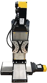
Image: PI L-511 XYZ stacked stage assembly. The vertically stacked axes and attached motors create a significant CG offset above the lowest bearing, illustrating the moment load challenges discussed in this article. Source: Physik Instrumente (PI)
Mounting best practices
1. Centre the CG over the stage
This is the most effective single action. Design the payload mounting bracket to position the assembly's CG as close as possible to the stage's geometric centre, both horizontally and vertically. A few millimetres of bracket redesign can reduce moment loads by 50% or more.
Practical approach: after calculating the CG, add a counterweight or reposition components to shift the CG toward the stage centre. For the optical payload example above, moving the illumination module from (−25, 10) to (5, 0) would shift CG_x from 5.6 mm to 9.2 mm (worse in X, actually) or redistributing the cable routing could shift CG_y. The point is to iterate on the design with the CG calculation in hand.
2. Minimize the CG height
Every millimetre of CG height amplifies the dynamic pitch moment. Design the payload to be as low-profile as possible:
- Mount heavy components (cameras, motors) close to the stage surface.
- Use folded optical paths (mirrors) to reduce the height of optical assemblies.
- Consider inverting the stage (mounting it upside down with the payload hanging below) if the application geometry permits. This reverses the sign of gravitational moments but does not eliminate them, and it places the CG below the bearing plane, which can be beneficial or detrimental depending on the bearing type.
3. Use an adapter plate to distribute the load
A stiff adapter plate between the payload and the stage spreads the mounting forces over a larger area and can incorporate features to constrain the payload's orientation. The adapter plate should be:
- Rigid (high moment of inertia): thick aluminium or steel, not a thin sheet
- Kinematically mounted to the payload to avoid over-constraining the assembly
- Bolted to the stage at multiple points distributed around the stage's mounting pattern
4. Manage cables and hoses
Cable bundles are a significant and often overlooked source of CG offset and moment load variation. A typical cable bundle for a camera and illumination system weighs 200 to 500 g and hangs off one side of the stage. Worse, the cable configuration changes as the stage moves, creating position-dependent moment loads.
Best practices for cable management:
- Route cables symmetrically where possible, with equal mass on each side of the stage.
- Use a cable carrier (energy chain) with a defined bend radius, mounted so that the cable carrier's weight is supported by the frame (not by the stage carriage).
- Minimize the cable loop height above the stage.
- Use flexible, lightweight cables (silicone-jacketed, fine-gauge) to reduce both mass and stiffness.
5. Account for dynamic loads in the mounting design
The mounting interface must withstand not only the static weight but also the inertial forces during acceleration. For a 5 kg payload accelerating at 10 m/s² (≈ 1 g), the horizontal inertial force is 50 N. The bolted connection between the payload and the stage must resist this force without slipping or loosening.
Minimum clamping force for friction-held payloads:
F_clamp = F_inertial / µ_friction
For steel on anodized aluminium, µ ≈ 0.3:
F_clamp = 50 / 0.3 = 167 N
This is easily achievable with two M4 bolts at moderate torque. However, if the payload is positioned by dowel pins, the pins (not friction) resist the inertial force, and the clamping force only needs to prevent lift-off.
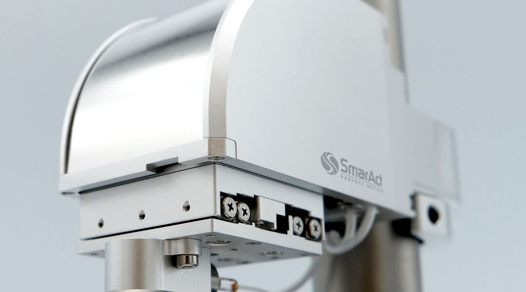
Image: SmarAct 3D positioning stage with a sensor head payload. The payload's CG sits well above and to one side of the stage's bearing plane, creating both pitch and roll moments that must be accounted for in the system design. Source: SmarAct
6. Characterize the actual moment loads before deployment
After assembling the complete payload on the stage, measure the actual CG location if possible. Simple methods include:
- Weight measurement: place the stage (without power) on a precision balance, and measure the weight distribution across the mounting feet. Asymmetric weight distribution indicates a CG offset.
- Tilt measurement: with the stage powered and position-locked, measure the carriage tilt using an electronic level or autocollimator. The tilt direction and magnitude indicate the direction and approximate magnitude of the moment load.
- Dynamic response: command a step motion and observe the settling behavior. A payload with significant CG offset will exhibit more ringing and longer settling time than a centred payload. If the settling time is significantly longer than the stage specification, excessive moment loading is a likely cause.
Worked example: maximum allowable CG offset
Given:
- Stage: 100 mm travel linear piezo stage
- Bearing: cross-roller, pitch stiffness K_pitch = 150 N·m/mrad
- Maximum specified moment (pitch): 3.0 N·m
- Accuracy specification: ±0.5 µm (with centred payload)
- Maximum acceleration: 5 m/s²
- Payload mass: 2 kg
Question: what is the maximum CG height and horizontal offset that maintains the accuracy specification?
Accuracy budget allocation: allow 200 nm (0.2 µm) of the ±0.5 µm accuracy budget for moment-induced error (the remaining 0.3 µm covers encoder errors, thermal drift, and other sources).
Static moment contribution: the maximum static pitch tilt for 200 nm error at CG height h is:
Δx = θ × h = (M_static / K_pitch) × h = (m × g × d_x / K_pitch) × h
We need Δx ≤ 200 nm during acceleration (worst case), so we must consider both static and dynamic moments:
Δx_total = (m × g × d_x + m × a × h) / K_pitch × h
Rearranging: 200 × 10⁻⁹ ≥ (2 × 9.81 × d_x + 2 × 5 × h) / 150 × h
This gives us a constraint relating d_x and h. Let's evaluate for a few cases:
Case 1: h = 50 mm, d_x = 0 (perfectly centred horizontally, CG elevated)
Δx = (0 + 2 × 5 × 0.050) / 150 × 0.050 = 0.5 / 150 × 0.050 = 3.33 × 10⁻³ mrad × 50 mm = 167 nm. Acceptable (under 200 nm).
Case 2: h = 50 mm, d_x = 10 mm
Δx = (2 × 9.81 × 0.010 + 0.5) / 150 × 50 = (0.196 + 0.5) / 150 × 50 = 0.696 / 150 × 50 = 4.64 × 10⁻³ × 50 = 232 nm. Exceeds 200 nm budget.
Case 3: h = 30 mm, d_x = 10 mm
Δx = (0.196 + 2 × 5 × 0.030) / 150 × 30 = (0.196 + 0.300) / 150 × 30 = 0.496 / 150 × 30 = 3.31 × 10⁻³ × 30 = 99 nm. Acceptable.
Conclusion for this stage and payload: to stay within the 200 nm accuracy allocation, keep the CG height below 50 mm if horizontally centred, or below 30 mm if the horizontal offset is 10 mm. These constraints are tighter than most engineers expect and illustrate why CG management matters for sub-micrometre applications.
Moment load check: for Case 1, the total moment during acceleration is:
M_total = 2 × 5 × 0.050 = 0.5 N·m (well within the 3.0 N·m maximum)
The accuracy limit is reached long before the bearing's moment capacity is exceeded. This is typical: accuracy degradation, not bearing overload, is the binding constraint for precision stages.
Effect on dynamic performance
CG offset affects not only static and quasi-static accuracy but also the stage's dynamic behavior.
Reduced usable acceleration
If the maximum allowable moment is M_max, and the CG height is h, the maximum acceleration before exceeding the moment limit is:
a_max = (M_max − m × g × d_x) / (m × h)
For the previous example (M_max = 3 N·m, m = 2 kg, h = 50 mm, d_x = 10 mm):
a_max = (3.0 − 2 × 9.81 × 0.010) / (2 × 0.050) = (3.0 − 0.196) / 0.100 = 28 m/s²
This is a high acceleration, so the moment limit is not the constraint here. But for heavier payloads or taller CG:
With m = 8 kg, h = 100 mm, d_x = 20 mm: a_max = (3.0 − 8 × 9.81 × 0.020) / (8 × 0.100) = (3.0 − 1.57) / 0.80 = 1.79 m/s²
This is a severe reduction. The stage, which might be capable of 10 m/s² with a centred load, can only accelerate at 1.8 m/s² before exceeding its moment limit. Throughput drops proportionally.
Resonant frequency shift
The stage's natural frequency depends on the effective mass and stiffness. An elevated CG lowers the effective pitch resonant frequency because the moment of inertia about the bearing increases as m × h². This lower resonance frequency requires lower servo bandwidth to avoid instability, which in turn reduces the controller's ability to reject disturbances and achieve fast settling.
The pitch resonant frequency scales approximately as:
f_pitch ∝ √(K_pitch / I_pitch)
where I_pitch = m × h². Doubling the CG height quadruples the moment of inertia and halves the pitch resonant frequency. If the original pitch resonance was at 400 Hz, doubling the CG height drops it to 200 Hz, potentially limiting the position servo bandwidth to 50 to 100 Hz (compared to 100 to 200 Hz with the original CG height).
Settling time increase
The combination of dynamic tilt and reduced pitch resonant frequency directly increases settling time. When the stage decelerates at the end of a move, the pitch moment from deceleration causes the payload to tilt. After the move completes, the tilt rings down at the pitch resonant frequency. The number of oscillation cycles to settle below the accuracy threshold determines the settling time.
For a pitch resonance at 200 Hz with 5% damping (Q = 10), the time to settle from a 500 nm initial perturbation to ±50 nm is approximately:
t_settle = ln(500/50) / (2π × 200 × 0.05) = 2.303 / 62.8 = 36.7 ms
At 400 Hz (centred payload), the settling time would be 18.3 ms. The elevated CG doubles the settling time, directly reducing the stage's throughput for point-to-point applications.
Summary
Payload CG offset is a system-level concern that affects every aspect of stage performance: accuracy, bearing life, dynamic capability, and settling time. The key principles are straightforward. Centre the CG. Keep it low. Calculate the moments before committing to a mechanical design. If the datasheet accuracy specification must be maintained, the moment-induced error must be included in the error budget, not ignored. For sub-micrometre applications, a CG offset of even 10 mm horizontally and 50 mm vertically can consume a significant fraction of the accuracy budget, as the worked examples demonstrate. Treating payload mounting as an afterthought is the fastest way to turn a high-performance stage into a mediocre one.