Applications / Semiconductor
Vacuum-compatible motor selection for process chambers
Outgassing, particles, magnetic fields, and material compatibility: the practical constraints that narrow your motor options in vacuum
Vacuum-Compatible Motor Selection for Process Chambers
Semiconductor process chambers operate at pressures ranging from rough vacuum (100 Pa) to ultra-high vacuum (10^-8 Pa). Motors inside or adjacent to these chambers must function reliably without contaminating the process environment. This constraint eliminates most off-the-shelf motors and demands careful evaluation of outgassing, particle generation, magnetic fields, thermal properties, and chemical compatibility.
For foundational coverage of vacuum operation, see vacuum and cleanroom operation. This article provides a practical framework for selecting motors in vacuum process environments, with specific attention to outgassing specifications, bakeout procedures, particle budgets, magnetic interference limits, and material compatibility with common process gases.
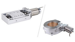
Image: Physik Instrumente (PI)
Vacuum Levels and Their Implications for Motor Design
Different semiconductor processes require different vacuum levels, and each level imposes distinct constraints on motor selection.
Rough Vacuum (100 to 1 Pa)
Processes: atmospheric pressure CVD (APCVD) loadlocks, wafer transfer chambers, some etch chambers during gas flow.
At these pressures, convective cooling still functions (weakly), and outgassing requirements are moderate. The primary concern is particle generation. Standard stepper motors with stainless steel housings and ceramic bearings can operate at this level if properly cleaned and baked. Piezoelectric motors are preferred when particle specifications are tight (below Class 1 per ISO 14644-1).
Medium Vacuum (1 to 10^-3 Pa)
Processes: plasma etch, physical vapor deposition (PVD) load/unload, ion implantation beam lines.
Convective cooling is negligible. Heat must be removed by conduction or radiation. Outgassing becomes a meaningful contributor to chamber base pressure. Motors must be fabricated from low-outgassing materials, and all organics (lubricants, adhesives, cable insulation) must be vacuum-rated. Piezoelectric motors and brushless DC motors with vacuum-rated windings are the primary options.
High Vacuum (10^-3 to 10^-7 Pa)
Processes: electron beam lithography, PVD deposition, molecular beam epitaxy (MBE), SEM inspection.
Outgassing requirements are stringent. Every component must be evaluated for total mass loss, collected volatile condensable material, and outgassing rate. Motors must withstand bakeout at 120 to 200 degrees Celsius. Lubricants are essentially prohibited; bearings must be dry (MoS2 coated, ceramic, or eliminated entirely via flexures). Piezoelectric actuators with inorganic adhesives or co-fired construction are the default choice.
Ultra-High Vacuum (below 10^-7 Pa)
Processes: MBE, some surface analysis tools, particle accelerator beam lines.
Only metals, ceramics, and glasses are acceptable. All organics must be eliminated. Bakeout temperatures of 200 to 350 degrees Celsius are standard. Conventional electromagnetic motors are essentially excluded unless their windings use ceramic or polyimide insulation rated for UHV bakeout. Piezoelectric actuators made from cofired PZT with platinum or palladium-silver electrodes and ceramic adhesives are the preferred solution.
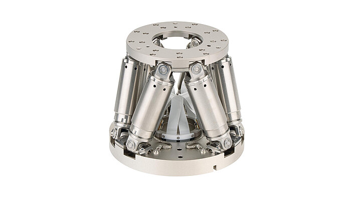
Image: Physik Instrumente (PI)
Outgassing: Specifications and Measurement
Outgassing is the release of gas molecules from solid surfaces and bulk materials in vacuum. It is the dominant gas load in clean vacuum systems and the primary way that motor materials can contaminate a process chamber.
Outgassing Metrics
Outgassing rate (q): Measured in PaL/(scm^2) or TorrL/(scm^2). This is the gas flux per unit surface area. For a motor with 100 cm^2 of exposed surface area, an outgassing rate of 10^-8 PaL/(scm^2) contributes a gas load of 10^-6 Pa*L/s. If the chamber has 500 L/s of pumping speed, this raises the base pressure by 2 x 10^-9 Pa, which is acceptable for most high-vacuum applications.
Total mass loss (TML): The percentage of mass lost by a material after 24 hours at 125 degrees Celsius in vacuum. NASA's ASTM E595 test is the standard. Materials with TML below 1.0% are generally acceptable for medium vacuum. High vacuum applications typically require TML below 0.5%.
Collected volatile condensable material (CVCM): The percentage of outgassed material that condenses on a 25 degree Celsius collector plate during the TML test. CVCM below 0.1% is the standard requirement. This metric specifically addresses the risk of outgassed material depositing on wafers, optics, or other sensitive surfaces.
Outgassing of Common Motor Materials
| Material | Outgassing rate after 24h bake at 150C (Pa*L/s/cm^2) | TML (%) | CVCM (%) | Notes |
|---|---|---|---|---|
| Stainless steel 316L (electropolished) | 10^-10 to 10^-9 | <0.01 | <0.01 | Excellent |
| PZT ceramic (cofired) | 10^-10 to 10^-9 | <0.01 | <0.01 | Excellent |
| Alumina (Al2O3) ceramic | 10^-11 to 10^-10 | <0.01 | <0.01 | Excellent |
| Polyimide (Kapton) | 10^-8 to 10^-7 | 1.0 to 1.5 | <0.01 | Acceptable for HV |
| PEEK | 10^-7 to 10^-6 | 0.2 to 0.5 | <0.05 | Marginal for HV |
| Epoxy (vacuum-rated) | 10^-8 to 10^-7 | 0.5 to 2.0 | 0.01 to 0.1 | Application-dependent |
| Silicone rubber | 10^-5 to 10^-4 | 3 to 10 | 0.5 to 5 | Unacceptable |
| Standard motor winding insulation | 10^-6 to 10^-5 | 1 to 5 | 0.1 to 1 | Unacceptable for HV |
The table reveals the challenge for electromagnetic motors. Standard winding insulation (typically polyester-imide or polyamide-imide enamel) outgases at levels unacceptable for high vacuum. Vacuum-rated electromagnetic motors use polyimide (Kapton) insulated wire, which reduces outgassing by 10x to 100x but increases cost and limits the maximum winding temperature.
Piezoelectric actuators, being primarily PZT ceramic and metal electrodes, have inherently low outgassing. The main concern is the adhesive used to bond the ceramic layers (in bonded stacks) or to attach the actuator to the stage structure. Cofired stacks eliminate interlayer adhesive entirely, using only the sintered ceramic-electrode interface. For mounting adhesive, vacuum-rated epoxies (such as Epo-Tek 353ND) or ceramic cements provide outgassing rates below 10^-8 PaL/(scm^2) after baking.
Bakeout Compatibility
Vacuum systems are baked (heated in vacuum) to accelerate outgassing and reduce the time to reach base pressure. The bakeout temperature and duration depend on the vacuum level required.
Bakeout Protocols by Vacuum Level
- Medium vacuum: 80 to 100 degrees Celsius for 8 to 24 hours. Removes adsorbed water and light hydrocarbons.
- High vacuum: 120 to 150 degrees Celsius for 24 to 48 hours. Removes adsorbed water, diffuses and releases dissolved gases from bulk materials.
- Ultra-high vacuum: 200 to 350 degrees Celsius for 24 to 72 hours. Removes deeply dissolved hydrogen from stainless steel, desorbs tightly bound water from oxide surfaces.
Motor Bakeout Limits
Piezoelectric actuators: The Curie temperature of PZT ceramics is 150 to 350 degrees Celsius, depending on composition. Standard "soft" PZT (PZT-5A type) has a Curie temperature around 350 degrees Celsius. However, the poling of the ceramic begins to degrade at temperatures above 50% to 70% of the Curie temperature, which places a practical limit of 150 to 200 degrees Celsius for continuous bakeout. Cofired stacks with high-Curie-temperature compositions can tolerate 200+ degrees Celsius.
The adhesive is often the limiting factor. Standard vacuum epoxies are rated to 150 to 200 degrees Celsius. Ceramic adhesives (sodium silicate, ceramic cements) tolerate 400+ degrees Celsius but are brittle and can crack under thermal cycling.
For UHV applications requiring 250+ degree Celsius bakeout, the solution is to locate the piezo actuators outside the bakeout zone (on a separately cooled feedthrough) or to use actuator compositions with Curie temperatures above 400 degrees Celsius. Some manufacturers offer PZT compositions with Curie temperatures of 400 to 500 degrees Celsius specifically for UHV applications.
Electromagnetic motors: Polyimide-insulated windings tolerate 250 to 300 degrees Celsius short-term and 200 degrees Celsius continuous. This is compatible with most HV bakeout protocols. However, the permanent magnets (NdFeB) in brushless DC motors begin to demagnetize above 80 to 150 degrees Celsius (depending on grade). SmCo magnets tolerate 250 to 350 degrees Celsius and are preferred for vacuum motor applications, despite their lower energy product.
The motor bearings present another bakeout challenge. Standard grease-lubricated bearings cannot be baked above 80 to 120 degrees Celsius. Dry-lubricated bearings (MoS2 or WS2 coated) tolerate 300+ degrees Celsius but have higher friction and shorter life than grease-lubricated bearings. For high vacuum applications, ceramic bearings (Si3N4 balls in stainless steel races) with solid film lubricant are standard.
Particle Contamination
Particles generated by motors can deposit on wafers, reducing yield. The allowable particle contribution depends on the process and the device technology node.
Particle Budget
For a front-end-of-line (FEOL) process at the 3 nm node, the total particle adder budget per process step is approximately 0.01 particles/cm^2 at sizes above 20 nm. For a 300 mm wafer (707 cm^2), this is 7 particles per wafer per process step.
The motor's particle contribution must be a small fraction of this budget, typically below 1 particle per wafer per process step. This translates to a particle generation rate of approximately 0.001 particles/(cm^2 * min) at the wafer surface, accounting for the transport efficiency between the motor and the wafer.
Particle Generation Mechanisms
Bearing wear: Rolling and sliding bearings generate particles through adhesive wear, abrasive wear, and fatigue spalling. Standard ball bearings generate 10^3 to 10^5 particles per revolution in the 0.1 to 10 micrometer size range. Even ceramic bearings with solid film lubricant generate 10 to 100 particles per revolution. In a motor spinning at 1000 RPM, this is 10,000 to 100,000 particles per minute, far exceeding the budget for any process chamber near the wafer.
Brush wear: Brushed DC motors are categorically excluded from process chamber environments due to brush wear particles.
Flexure fatigue: Flexure-guided stages with piezoelectric actuators generate zero particles during normal operation because there are no sliding or rolling contacts. Over millions of cycles, flexure fatigue can generate microscopic cracks, but these do not produce free particles unless the flexure actually fractures.
Outgassing condensation: Outgassed organic molecules can nucleate into nanoparticles under certain conditions (UV exposure, plasma environments). This is another reason to minimize organic content in motor assemblies.
Motor Ranking for Particle Performance
- Piezoelectric actuator with flexure stage: Zero particle generation. Best for all vacuum levels.
- Piezoelectric stepping motor (stick-slip): Low particle generation. The friction interface can generate particles, but at rates 100x to 1000x below bearings. Acceptable for medium and some high vacuum applications with careful material selection.
- Brushless DC motor with magnetic bearings: Zero particle generation from the motor itself, but magnetic bearing controllers add complexity.
- Brushless DC motor with ceramic bearings: Low to moderate particle generation. Acceptable for rough vacuum and some medium vacuum applications. Not recommended when the motor is in the direct particle transport path to the wafer.
- Stepper motor with standard bearings: Moderate particle generation. Acceptable only in rough vacuum loadlock and transfer chambers.
Magnetic Field Limits
Many semiconductor processes are sensitive to magnetic fields. Electron beams (in e-beam lithography and SEM inspection) are deflected by stray fields. Plasma processes can be affected by magnetic fields that alter ion trajectories. Some metrology tools (such as MOKE-based film thickness measurement) require magnetically quiet environments.
Field Sensitivity by Application
| Application | Maximum stray field at process point | Typical distance from motor |
|---|---|---|
| SEM/TEM inspection | 0.1 to 1 microtesla | 100 to 500 mm |
| E-beam lithography | 0.01 to 0.1 microtesla | 200 to 1000 mm |
| Plasma etch | 10 to 100 microtesla | 50 to 300 mm |
| Ion implant | 1 to 10 microtesla | 200 to 500 mm |
| PVD (magnetron) | 100+ microtesla (magnets present by design) | N/A |
| Metrology (non-magnetic) | 1 to 10 microtesla | 100 to 500 mm |
Magnetic Fields from Motor Types
Piezoelectric actuators: Zero DC magnetic field. Zero AC magnetic field during operation. The drive voltage produces negligible current through the ceramic (PZT is an insulator), so no magnetic field is generated. This makes piezo actuators the only motor technology that contributes zero magnetic interference.
Brushless DC motors (with NdFeB or SmCo magnets): Strong DC magnetic field from permanent magnets. A typical motor with NdFeB magnets produces a stray field of 100 to 1000 microtesla at 100 mm distance, depending on motor size and magnetic circuit design. Even with magnetic shielding (mu-metal housing), the residual field at 100 mm is typically 1 to 10 microtesla.
The AC field from motor current is typically 1 to 10 microtesla at 100 mm during operation, at frequencies related to the commutation rate (motor speed x number of pole pairs).
Stepper motors: Similar DC field to brushless DC motors. AC fields at step frequencies can be problematic for sensitive measurements.
Voice coil actuators (without permanent magnets): Zero DC field when not energized. AC field proportional to drive current during operation. Fields of 0.1 to 1 microtesla at 100 mm are typical. Shielding is easier because there is no permanent magnet field to contain.
For applications with stray field limits below 1 microtesla, piezoelectric actuators are the only practical choice for motors within 500 mm of the process point. Electromagnetic motors can be used if they are located farther away (1000+ mm) or enclosed in heavy magnetic shielding, but both approaches add cost and complexity.
Material Compatibility with Process Gases
Semiconductor process chambers use a variety of reactive gases that can attack motor materials. The motor must either be sealed from the process gas environment or constructed from compatible materials.
Common Process Gases and Their Corrosive Effects
Chlorine-based etch gases (Cl2, BCl3, HCl): Aggressively attack aluminum, copper, and many organic materials. Stainless steel 316L is moderately resistant. Hastelloy, Inconel, and ceramics (alumina, PZT) are resistant. Chlorine plasmas produce atomic chlorine and chlorine ions that penetrate deeper than molecular chlorine.
Fluorine-based etch gases (CF4, SF6, NF3, CHF3): Attack silicon, silicon dioxide, and many metals. Stainless steel is moderately resistant. Aluminum (with anodized coating), nickel alloys, and ceramics are resistant. Fluorine plasmas are particularly aggressive and can attack even PTFE at elevated temperatures.
Oxygen plasmas (O2, O3): Attack all organic materials. Used intentionally for photoresist stripping. Motor insulation, adhesives, and cable jackets exposed to oxygen plasma will degrade rapidly. Only metals and ceramics survive long-term exposure.
NH3, H2S, and other corrosive gases: Used in MOCVD and ALD processes. Attack copper, silver, and some brazing alloys. Gold, platinum, and stainless steel are resistant.
Motor Material Compatibility Strategy
The safest approach is to isolate the motor from the process gas entirely. This is done by:
-
Bellows-sealed feedthroughs: The motor sits outside the chamber and transmits motion through a bellows-sealed mechanical feedthrough. The bellows (stainless steel or Inconel) provides a hermetic seal while allowing linear or rotary motion. This adds cost, complexity, and compliance (reduced stiffness) to the motion system.
-
Magnetically coupled feedthroughs: For rotary motion, a magnetic coupling transmits torque through the chamber wall without a physical seal. Zero leak rate, but limited torque capacity and susceptible to temperature-induced demagnetization.
-
Encapsulated motors: The motor is inside the chamber but sealed in a gas-tight enclosure (stainless steel or ceramic). The enclosure is purged with inert gas (N2 or Ar) to prevent process gas ingress. This approach works for electromagnetic motors but adds thermal management challenges (heat from the motor is trapped inside the enclosure).
-
Inherently compatible motors: Piezoelectric actuators constructed entirely from PZT ceramic, alumina insulators, and stainless steel or Inconel housings are inherently compatible with most process gases. No encapsulation is needed if the adhesive and wiring materials are also compatible. Cofired PZT stacks with platinum electrodes and ceramic-insulated leads resist all common semiconductor process gases.
Worked Example: Motor Selection for an Etch Chamber Wafer Lift Stage
Consider selecting a motor for a wafer lift stage inside a chlorine-based etch chamber. The stage raises and lowers the wafer (travel: 50 mm; payload: 500 g; accuracy: 10 micrometers; vacuum: 1 Pa during process, 10^-3 Pa at base).
Requirements summary:
- Travel: 50 mm
- Payload: 500 g (wafer + carrier)
- Positioning accuracy: 10 micrometers
- Speed: 10 mm/s
- Vacuum: 1 Pa (process), 10^-3 Pa (base)
- Temperature: 25 to 80 degrees Celsius (chamber wall)
- Process gas: Cl2/BCl3 plasma
- Particle budget: <0.1 particles/cm^2 per lift cycle at >30 nm
- Magnetic field limit: none (no e-beam or sensitive metrology)
Option A: Bellows-sealed stepper motor
A standard stepper motor outside the chamber drives a lead screw through a bellows-sealed feedthrough. The motor is in atmosphere and faces no vacuum, outgassing, or chemical compatibility constraints.
Pros: Low cost, wide availability, 10 micrometer accuracy achievable with microstepping. Cons: Bellows adds compliance (reduces stiffness and positioning accuracy). Lead screw and bellows generate particles (typically 10 to 100 per cycle). Bellows has finite cycle life (10^6 to 10^8 cycles depending on stroke and material).
Option B: Vacuum-rated brushless DC motor with ceramic bearings
A compact brushless DC motor with SmCo magnets, polyimide-insulated windings, and Si3N4 bearings operates inside the chamber.
Pros: Direct drive eliminates bellows compliance. Good speed and accuracy. Cons: Outgassing from polyimide insulation (marginal at 10^-3 Pa base). Particle generation from bearings (10 to 100 per revolution). SmCo magnets may be attacked by chlorine plasma over time. Requires shielding or distance from process gas.
Option C: Piezoelectric stepping motor with ceramic slider
An inertial (stick-slip) piezo motor with an alumina slider and PZT stack actuator operates inside the chamber. No bearings, no magnets, no organic insulation.
Pros: Zero magnetic field. Minimal outgassing (PZT + alumina + stainless steel). Low particle generation (alumina-on-alumina friction interface generates ceramic particles at 10 to 100x lower rate than metallic bearings). Inherently compatible with chlorine chemistry. Cons: Limited force (typically 1 to 10 N; sufficient for 500 g payload). Slower than electromagnetic motors at long travel (50 mm may take 1 to 5 seconds). Requires closed-loop encoder for 10 micrometer accuracy.
Option D: Piezoelectric stack actuator with flexure stage
A PZT stack actuator drives a flexure-guided stage. No friction interfaces at all.
Pros: Zero particles. Zero magnetic field. Lowest outgassing. Compatible with all process gases. Fastest settling to 10 micrometer accuracy. Cons: Limited travel. A 50 mm stroke is far beyond the range of a single piezo stack (typically 0.1% of stack length = 50 micrometers for a 50 mm stack). This option is not viable for 50 mm travel without a mechanical amplifier that would reintroduce complexity.
Recommendation for this application: Option C (piezoelectric stepping motor) provides the best balance of vacuum compatibility, particle performance, chemical resistance, and travel range. For faster cycle times, Option A (bellows-sealed stepper) is acceptable if the particle budget permits the bellows and lead screw contribution, and if the bellows compliance does not degrade accuracy beyond the 10 micrometer specification.
Practical Selection Decision Tree
The following decision sequence helps narrow the motor choice for a given vacuum application:
-
What is the vacuum level?
- Rough vacuum (>1 Pa): Most motor types acceptable. Focus on particle performance.
- Medium vacuum (1 to 10^-3 Pa): Vacuum-rated motors required. Outgassing analysis needed.
- High vacuum (<10^-3 Pa): Only vacuum-designed motors. Bakeout compatibility required.
- Ultra-high vacuum (<10^-7 Pa): Only metal/ceramic construction. Piezo or UHV-rated electromagnetic.
-
Is there a magnetic field limit?
- Below 1 microtesla at process point: Piezoelectric actuators only (within 500 mm).
- 1 to 100 microtesla: Shielded electromagnetic or piezoelectric.
- Above 100 microtesla: Any motor type.
-
What is the particle budget?
- Zero particles (e.g., reticle handling, mask inspection): Flexure-guided piezo stage.
- Low particles (<1 per cycle): Piezo stepping motor or bellows-sealed external motor.
- Moderate particles acceptable: Vacuum-rated electromagnetic motor with ceramic bearings.
-
Is the motor exposed to process gas?
- Yes: Use inherently compatible materials (PZT, alumina, stainless steel, Inconel) or seal the motor.
- No (sealed or external): Material compatibility is less critical.
-
What travel range and speed are required?
- Sub-millimeter travel, high bandwidth: Piezo stack with flexure. Best accuracy and speed for short range.
- Millimeter to centimeter travel, moderate speed: Piezo stepping motor.
- Centimeter to meter travel, high speed: Electromagnetic motor (external with feedthrough, or vacuum-rated internal).
This decision tree is a starting point. Specific applications may have additional constraints (temperature range, radiation tolerance, cost, size) that modify the selection. But for the majority of semiconductor process chamber motor applications, the combination of vacuum, particle, and magnetic field requirements pushes the selection strongly toward piezoelectric solutions, particularly for motors located inside the chamber near the wafer.
Summary of Motor Technologies for Vacuum
| Parameter | Piezo stack + flexure | Piezo stepping motor | Brushless DC (vacuum) | Stepper (bellows-sealed) |
|---|---|---|---|---|
| Travel range | 1 to 200 micrometers | 10 to 100 mm | Unlimited (rotary) or 10 to 1000 mm (linear) | Unlimited with lead screw |
| Resolution | <0.1 nm | 1 to 50 nm | 10 to 1000 nm | 1 to 50 micrometers |
| Bandwidth | 100 to 5000 Hz | 1 to 20 kHz step rate | 100 to 5000 Hz | 1 to 100 Hz |
| Outgassing | Excellent | Excellent | Moderate to good | N/A (external) |
| Particles | Zero | Low | Moderate | Moderate (bellows + screw) |
| Magnetic field | Zero | Zero | High (requires shielding) | High (requires shielding) |
| Process gas compatibility | Excellent | Good to excellent | Poor to moderate | N/A (external) |
| Bakeout temperature | 150 to 200 C | 150 to 200 C | 80 to 150 C (magnets limit) | N/A (external) |
| Relative cost | Medium to high | Medium | Medium | Low |
The table makes clear why piezoelectric actuators dominate vacuum motor applications in semiconductor equipment. They are the only technology that simultaneously achieves zero particles, zero magnetic field, excellent outgassing, and broad chemical compatibility. When travel range requirements exceed piezo stack capabilities, piezo stepping motors extend the range while preserving most of the vacuum advantages. Electromagnetic motors remain the choice for long-travel, high-speed axes where they can be isolated from the process environment through feedthroughs or enclosures.