Applications / Optics & Photonics
Interferometer reference arm stability: thermal and vibration rejection in piezo mounts
Quantifying the path length stability requirements for precision interferometry and how piezoelectric mounts achieve them
Interferometer Reference Arm Stability: Thermal and Vibration Rejection in Piezo Mounts
Precision interferometers measure displacement, surface topography, refractive index, and a wide range of physical quantities by comparing the optical path length of a measurement beam with that of a reference beam. The measurement sensitivity depends directly on the stability of the reference arm. Any uncontrolled path length change in the reference arm appears as a spurious signal indistinguishable from a real measurement, imposing a noise floor on the interferometer's performance.
For a HeNe-based displacement interferometer operating at 632.8 nm, a 1 nm path length change in the reference arm produces a phase shift of 2 * pi * (1 / 632.8) * 2 = 0.020 radians (double pass). Modern interferometers resolve phase shifts of 0.001 to 0.01 radians, corresponding to path length resolution of 0.03 to 0.3 nm. The reference arm must be stable to this level, or better, for the interferometer to achieve its design resolution. See repeatability vs. accuracy for how these resolution figures relate to positioning specifications.
This article examines the path length stability requirements for different interferometric applications, the thermal and vibrational disturbances that threaten stability, and how piezoelectric mirror mounts provide both passive stiffness and active compensation to achieve the required performance.
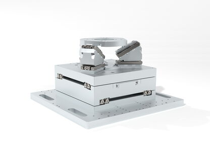
Image: SmarAct GmbH
Path Length Stability Requirements by Application
Different interferometric techniques impose different stability requirements, spanning five orders of magnitude from micrometers to sub-angstroms.
Displacement Interferometry (Metrology)
Used in: coordinate measuring machines (CMMs), semiconductor lithography stages, precision machining.
Required path length stability: 0.1 to 1 nm over measurement duration (milliseconds to seconds).
The reference arm is typically a fixed retroreflector mounted on the interferometer base. The measurement arm follows the moving stage. Any vibration or thermal drift of the reference retroreflector directly adds to the displacement measurement error.
Surface Profiling (Phase-Shifting Interferometry)
Used in: optical flat testing, lens metrology, semiconductor wafer flatness.
Required path length stability: 0.5 to 5 nm over the phase-shifting sequence (0.1 to 10 seconds).
Phase-shifting interferometry acquires multiple frames with known reference mirror displacements (typically lambda/4 per step). The phase-shifting actuator itself is typically a piezo stack pushing the reference mirror. The stability requirement here is for the reference arm to hold its position precisely between commanded steps.
Fourier Transform Spectroscopy (FTIR)
Used in: chemical analysis, atmospheric monitoring, astronomy.
Required path length stability: 1 to 100 nm over the scan duration (0.1 to 100 seconds).
The reference arm in an FTIR instrument is a scanning mirror that must move with uniform velocity. Path length errors produce ghost lines and spectral artifacts. The HeNe reference laser tracks the mirror position, and any vibration of the reference retroreflector (separate from the scanning mirror) adds noise to the position measurement.
Gravitational Wave Detection
Used in: LIGO, Virgo, KAGRA.
Required path length stability: 10^-19 meters RMS in the 10 to 1000 Hz band.
This is the most extreme stability requirement in any interferometric application. The reference (and measurement) mirrors are suspended as free masses on multi-stage pendulum isolators. Piezoelectric actuators provide active damping of the pendulum modes and fine alignment of the suspended optics. The stability requirements for these actuators are set not by the overall detector sensitivity (which is dominated by quantum shot noise and thermal noise of the mirror coatings) but by the need to keep the interferometer within its linear operating range.
Optical Coherence Tomography (OCT)
Used in: retinal imaging, industrial inspection.
Required path length stability: 1 to 10 nm over the A-scan time (1 to 100 microseconds for swept-source OCT; 1 to 10 milliseconds for time-domain OCT).
The reference arm in OCT contains a fixed mirror (for swept-source) or a scanning mirror (for time-domain). Vibration of the reference mirror during the A-scan produces axial resolution degradation and image artifacts.
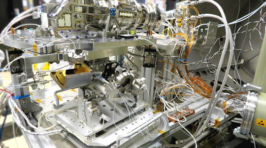
Image: SmarAct GmbH
Thermal Expansion Budgets
Thermal expansion is the dominant source of slow (DC to 1 Hz) path length drift in interferometer reference arms. Every material in the optical path expands or contracts with temperature, and the total path length change is the integral of these expansions along the beam path.
Thermal Sensitivity Analysis
For a reference arm consisting of a beam splitter, a reference mirror, and a mount structure, the total thermal path length change is:
delta_L = sum(alpha_i * L_i * delta_T)
where alpha_i is the CTE of the i-th component, L_i is its length along the beam path, and delta_T is the temperature change.
Example: A Michelson interferometer with a 100 mm reference arm.
| Component | Material | CTE (ppm/K) | Length (mm) | delta_L per K (nm) |
|---|---|---|---|---|
| Beam splitter substrate | BK7 | 7.1 | 25 | 178 |
| Air path | Air (refractive index) | ~1 ppm/K (dn/dT) | 75 | 75 |
| Reference mirror mount | Aluminum | 23 | 50 | 1150 |
| Mirror substrate | Fused silica | 0.55 | 6 | 3.3 |
| Total | ~1406 |
A 1 degree Celsius temperature change produces 1.4 micrometers of path length change. For a 0.1 nm stability requirement, the temperature must be controlled to within 0.1 / 1406 = 0.000071 degrees Celsius, or about 70 microkelvins. This is far beyond the capability of conventional laboratory temperature control (which achieves 0.01 to 0.1 degree Celsius stability).
Thermal Design Strategies
Low-CTE materials: Replacing the aluminum mirror mount with Invar (CTE = 1.2 ppm/K) or Zerodur (CTE = 0.05 ppm/K) dramatically reduces thermal sensitivity.
| Mirror mount material | CTE (ppm/K) | delta_L per K (nm) for 50 mm mount | Total delta_L per K (nm) |
|---|---|---|---|
| Aluminum | 23 | 1150 | 1406 |
| Stainless steel | 16 | 800 | 1056 |
| Invar | 1.2 | 60 | 316 |
| Super Invar | 0.3 | 15 | 271 |
| Zerodur | 0.05 | 2.5 | 259 |
With a Zerodur mount, the total thermal sensitivity drops to 259 nm/K, dominated by the BK7 beam splitter and the air path. Further improvement requires replacing the beam splitter with a fused silica or Zerodur substrate and operating in vacuum (to eliminate the air path thermal contribution).
Symmetric thermal design: If the measurement and reference arms are constructed symmetrically from the same materials, their thermal expansions cancel. A common-path interferometer (where both beams traverse the same optics) achieves this naturally. For a Michelson interferometer, making the measurement and reference arms the same length and from the same materials reduces the thermal sensitivity to the temperature difference between the arms, rather than the absolute temperature change.
Thermal shielding: Enclosing the reference arm in a thermal shield (insulated enclosure) reduces the rate of temperature change. A well-designed shield with 10 to 100 J/K thermal mass and 0.01 to 0.1 W/K thermal conductance to the environment has a thermal time constant of 100 to 1000 seconds. This converts rapid temperature fluctuations (from HVAC systems, human proximity, etc.) into slow drifts that are easier to track and compensate.
Vibration Sources and Their Impact
Vibration is the dominant source of fast (1 Hz to 10 kHz) path length disturbance in interferometer reference arms.
Common Vibration Sources
Building vibration: Floor vibration in a laboratory is typically 10 to 100 nm RMS in displacement (1 to 100 Hz band), depending on the building construction, nearby traffic, and machinery. This vibration transmits through the optical table legs to the interferometer base and from there to the reference mirror mount.
Optical table vibration: An undamped optical table has resonances in the 100 to 500 Hz range with Q factors of 50 to 200. Broadband floor vibration excites these resonances, producing displacement amplitudes of 1 to 10 nm at the table surface. Damped (honeycomb) optical tables reduce the Q factor to 10 to 50, and pneumatic isolation legs attenuate floor vibration by 20 to 40 dB above their natural frequency (typically 1 to 2 Hz).
Acoustic vibration: Airborne acoustic noise at 60 to 70 dBA produces pressure fluctuations of 20 to 60 mPa. These fluctuations cause two effects: (1) direct force on the mirror surface (pressure * area = 20 mPa * 0.001 m^2 = 20 micronewtons for a 25 mm mirror), producing displacement at the mirror's mechanical compliance; and (2) refractive index fluctuations in the air path (dn/dP = 2.7 * 10^-9 /Pa at 632.8 nm), producing path length changes of 2.7 * 10^-9 * 0.02 * 0.1 m = 5.4 * 10^-12 m = 0.005 nm per meter of air path per 20 mPa pressure fluctuation. For a 100 mm air path, this is 0.0005 nm, negligible for most applications.
Equipment vibration: Pumps, fans, compressors, and other equipment generate vibrations at their operating frequencies and harmonics. These are transmitted through the floor and building structure. A rotary pump at 1800 RPM (30 Hz) produces floor vibration at 30 Hz and multiples (60, 90, 120 Hz, etc.). The amplitude depends on distance and building structure, typically 1 to 50 nm at 10 m distance.
Vibration Transfer to the Reference Mirror
The path length sensitivity of the reference arm to vibration depends on the mechanical design of the mirror mount.
For a rigid mount (mirror bolted directly to the optical table), the mirror displacement equals the table displacement at the mounting point. If the table has 5 nm RMS displacement at 100 Hz, the reference mirror has 5 nm RMS displacement at 100 Hz.
However, the path length change depends on the relative displacement between the reference mirror and the beam splitter (and the measurement mirror). If both are mounted on the same rigid table, their displacements are equal, and the path length change is zero (common-mode rejection). The path length error arises from differential displacement between the components.
The differential displacement depends on the table's flexibility and the distance between the components. For two components separated by 200 mm on a table with a first bending mode at 200 Hz and Q = 50, the differential displacement is approximately:
delta_L_diff = L_separation * theta_table
where theta_table is the table surface tilt angle at the measurement frequency. For a 1 m optical table with 5 nm surface displacement at 200 Hz, the surface tilt is approximately:
theta = displacement / (table_length / pi) = 5 * 10^-9 / (1 / pi) = 15.7 nanoradians
The differential displacement between two points 200 mm apart is:
delta_L_diff = 0.2 * 15.7 * 10^-9 = 3.1 * 10^-9 m = 3.1 nm
This 3.1 nm differential displacement directly adds to the interferometer path length noise. For sub-nm stability, either the table vibration must be reduced (better isolation) or the components must be mounted closer together (shorter reference arm).
Piezo Mount Design for Interferometers
Piezoelectric mirror mounts serve two functions in interferometer reference arms: (1) high-stiffness passive support that minimizes vibration coupling, and (2) active compensation that drives the mirror to cancel residual path length disturbances.
Passive Stiffness Advantage
A conventional kinematic mirror mount (spring-loaded with adjustment screws) has a stiffness of 0.1 to 10 N/micrometer and a first resonance of 50 to 500 Hz. These mounts amplify vibrations near their resonance frequency by the Q factor (typically 10 to 50), producing path length amplification of 10 to 50x at the resonant frequency.
A piezo-driven mirror mount replaces the spring-loaded adjusters with piezo stack actuators preloaded against the mirror. The stiffness of a piezo stack (50 to 500 N/micrometer) is 10x to 100x higher than a spring-loaded adjuster. This pushes the mount resonance to 1 to 10 kHz, well above the typical vibration spectrum, and reduces the Q-amplified response at the resonant frequency.
For a 25 mm mirror (mass 10 g) on a piezo mount with effective stiffness of 100 N/micrometer:
f_res = (1 / (2 * pi)) * sqrt(100 * 10^6 / 0.01) = 15.9 kHz
At this resonance frequency, floor and table vibrations (which are concentrated below 500 Hz) are attenuated rather than amplified. The passive vibration rejection of the piezo mount, compared to a spring mount with 200 Hz resonance, is:
Rejection at 100 Hz = (f_res_piezo / f_res_spring)^2 = (15900 / 200)^2 = 6320x = 76 dB
This 76 dB of passive rejection means that 10 nm of table vibration at 100 Hz produces only 0.0016 nm of mirror vibration, far below the interferometer noise floor.
Active Path Length Compensation
For applications requiring sub-nm stability over long time scales (where thermal drift dominates), the piezo mount provides active compensation. A feedback loop measures the reference arm path length error and drives the piezo actuator to cancel it.
The path length error can be measured by:
Heterodyne interferometry: A secondary interferometer (using a different laser frequency or modulation scheme) monitors the reference arm path length independently of the main measurement. This requires additional optics and electronics but provides a direct, high-bandwidth measurement of the reference arm drift.
Common-mode monitoring: Two adjacent interferometer channels share the same reference arm. The difference between their measurements isolates the reference arm drift from the measurement signal. This technique is common in multi-axis displacement interferometers for lithography stages.
Temperature feedforward: Temperature sensors on the reference arm structure provide a feedforward signal to the piezo actuator. The actuator displacement is commanded as:
d_piezo = -(alpha_eff * L_eff * delta_T)
where alpha_eff and L_eff are the effective CTE and length of the reference arm structure. This open-loop approach compensates the first-order thermal drift without requiring a path length sensor, but its accuracy is limited by the precision of the thermal model and the temperature measurement.
Active Compensation Performance
The performance of active path length compensation depends on the loop bandwidth and the disturbance spectrum.
Thermal drift compensation: Thermal drift has a spectrum concentrated below 0.1 Hz. A piezo feedback loop with 1 Hz bandwidth provides 20 dB of rejection at 0.1 Hz, reducing a 100 nm thermal drift to 10 nm. A 10 Hz bandwidth provides 40 dB of rejection at 0.1 Hz, reducing the drift to 1 nm.
Vibration compensation: Vibration above the passive mount rejection frequency (say, above 10 kHz for a stiff piezo mount) is not a concern. Vibration between 1 Hz and 10 kHz is already attenuated by the stiff mount. Vibration below 1 Hz (from thermal effects or slow mechanical relaxation) is compensated by the active feedback loop.
The combined passive-plus-active system achieves path length stability of 0.01 to 1 nm RMS over bandwidths of DC to 10 kHz, depending on the specific implementation. This performance meets the requirements of all but the most demanding interferometric applications (gravitational wave detection, which uses much more elaborate isolation systems).
Piezo Actuator Specifications for Reference Arm Compensation
The piezo actuator in a reference arm compensator has modest requirements compared to other piezo applications (such as wafer stage positioning), because the disturbances are small and slow.
Travel Range
The actuator must accommodate the expected thermal drift plus a margin for alignment and settling. For a Zerodur-mounted reference arm with 260 nm/K thermal sensitivity and a 2 degree Celsius temperature range, the thermal drift is 520 nm. A piezo actuator with 5 to 10 micrometers of travel provides ample range.
For an aluminum-mounted reference arm (1400 nm/K) over a 5 degree Celsius range, the drift is 7 micrometers, requiring a 10 to 20 micrometer actuator. This is still a modest requirement for a multilayer piezo stack.
Resolution
The actuator resolution must match the path length stability requirement. For 0.1 nm path length stability, the actuator must achieve 0.1 nm displacement resolution. In closed-loop operation with a capacitive sensor, this is achievable with standard piezo stacks and low-noise amplifiers.
In open-loop (voltage-driven) operation, the resolution is limited by amplifier noise. For an amplifier with 100 microvolt RMS noise driving a stack with 10 nm/V sensitivity, the open-loop position noise is 1 pm RMS, far exceeding the 0.1 nm requirement.
Bandwidth
The required bandwidth is set by the disturbance spectrum. For thermal drift compensation, 1 to 10 Hz is sufficient. For vibration compensation (in addition to the passive mount stiffness), 100 to 1000 Hz may be needed.
The piezo actuator bandwidth is determined by the mount resonance (discussed above). For a stiff piezo mount with 10+ kHz resonance, the actuator can provide 1 to 3 kHz of closed-loop compensation bandwidth, far exceeding the typical requirement.
Power Dissipation
For reference arm compensation, the actuator operates near its center position with small deviations (tens to hundreds of nanometers). The power dissipation is negligible: for a 1 microfarad piezo driven at 10 nm amplitude at 100 Hz, the power is:
P = pi * f * C * V_pk^2 = pi * 100 * 10^-6 * (0.001)^2 = 3.1 * 10^-10 W
This negligible power dissipation means the piezo actuator itself contributes essentially zero heat to the reference arm, which is critical for thermal stability.
Practical Design Examples
Example 1: Phase-Shifting Interferometer for Optical Testing
A Fizeau interferometer tests optical flats to lambda/100 accuracy (6.3 nm at 632.8 nm). The reference surface is the rear surface of the transmission flat. The phase-shifting actuator moves the reference surface through four steps of lambda/4 (158.2 nm per step).
Stability requirement: The reference surface must hold each step position to within lambda/1000 = 0.63 nm during the camera integration time (10 to 100 ms).
Actuator design: A three-actuator piezo mount (tripod configuration) supports the transmission flat. Each actuator is a multilayer PZT stack with 20 micrometers of travel and 200 N/micrometer stiffness. The mount supports a 100 mm diameter, 20 mm thick fused silica flat (mass: 690 g).
Mount resonance: approximately 2.7 kHz (calculated from total stiffness of 600 N/micrometer and 690 g mass, accounting for the three-actuator geometry).
In-position stability: with a stiff mount and no active vibration during integration, the reference surface stability is limited by floor vibration attenuated by the optical table and the mount. For a well-isolated table (5 nm floor vibration reduced to 0.5 nm at the table surface at 100 Hz), the mount attenuation at 100 Hz is (2700/100)^2 = 729x, giving 0.5 / 729 = 0.0007 nm reference surface vibration. This is far below the 0.63 nm requirement.
Step accuracy: The piezo actuators must step by exactly lambda/4 = 158.2 nm. With closed-loop capacitive sensors (0.5 nm resolution), the step accuracy is within 0.5 nm, meeting the lambda/1000 requirement.
Thermal drift between steps: If the four-step acquisition takes 1 second and the temperature changes by 0.001 degree Celsius during that second, the Zerodur mount contributes 0.05 * 10^-6 * 50 mm * 0.001 = 0.0025 nm of drift, negligible.
Example 2: Heterodyne Displacement Interferometer for Stage Metrology
A heterodyne interferometer measures the displacement of a lithography wafer stage over 300 mm of travel with 0.1 nm resolution. The reference arm consists of a corner cube retroreflector mounted on the interferometer base.
Stability requirement: 0.1 nm reference arm path length stability over 10 ms measurement windows, and below 1 nm drift over 1 hour.
Thermal design: The reference retroreflector is mounted on a Super Invar bracket (CTE = 0.3 ppm/K) with a 30 mm path length inside the bracket. The thermal sensitivity is 0.3 * 10^-6 * 30 mm = 0.009 nm/mK. For 1 nm drift over 1 hour, the allowable temperature change is 1 / 0.009 = 111 millikelvins. Laboratory temperature control to +/- 0.05 degrees Celsius (50 millikelvins) keeps the drift within 0.45 nm.
Vibration design: The retroreflector (mass 20 g) is bonded directly to the Super Invar bracket with vacuum-grade epoxy (stiffness approximately 500 N/micrometer at the bond interface). The mount resonance is approximately 25 kHz. Table vibration of 1 nm at 200 Hz is attenuated by (25000/200)^2 = 15,625x, giving 0.00006 nm reference arm vibration. Negligible.
Active compensation: Not needed for this application. The passive stiffness and low-CTE material provide sufficient stability.
Example 3: Scanning White-Light Interferometer with Active Reference
A scanning white-light interferometer (SWLI) for surface roughness measurement scans the reference mirror over 200 micrometers of travel with 0.1 nm resolution. The scanning actuator is a piezo stack, and the reference mirror mount must provide both scanning motion and position stability.
Stability requirement: 0.5 nm path length accuracy over the full 200 micrometer scan range.
Actuator design: A single multilayer piezo stack (10 x 10 x 30 mm, 200 V, approximately 30 micrometers free stroke) is insufficient for 200 micrometers of travel. Two options:
-
A piezo stack with a flexure amplifier (amplification ratio 7x) provides 210 micrometers of travel, but the amplified stiffness drops to 200 / 49 = 4 N/micrometer (stiffness divides by the square of the amplification ratio). With a 50 g mirror, the resonance is approximately 1.4 kHz. Adequate for scanning at up to 100 Hz.
-
A piezo linear motor (stick-slip type) provides unlimited travel with 1 to 5 nm resolution. Scanning speed is limited to about 1 mm/s. For a 200 micrometer scan, the scan time is 0.2 seconds. This is acceptable for many SWLI applications.
Linearity: The piezo stack has 10% to 15% hysteresis. For 0.5 nm accuracy over 200 micrometers, the positioning accuracy must be 0.5 / 200000 = 0.00025%, which is impossible open-loop. Closed-loop operation with a laser interferometer monitoring the reference mirror position achieves the required accuracy by using the interferometer signal (from a separate HeNe laser) as the position feedback.
Example 4: Gravitational Wave Detector Alignment Actuator
The LIGO interferometer uses piezoelectric actuators on the suspended mirror mounts for initial alignment and low-frequency control. The actuators push against the mirror suspension frame (not the mirror itself, which must be a free mass at detection frequencies).
Requirements:
- Travel: 10 to 100 micrometers (for initial alignment)
- Bandwidth: DC to 10 Hz (alignment servo)
- Noise: below 10^-15 m/sqrt(Hz) at 10 Hz (to avoid injecting noise into the detection band)
The noise requirement is extraordinary. A standard piezo amplifier with 100 microvolt/sqrt(Hz) noise density driving a stack with 10 nm/V sensitivity would produce 10^-12 m/sqrt(Hz) of displacement noise, which is three orders of magnitude too high.
The solution uses a multi-stage actuation hierarchy: piezo actuators provide coarse alignment (micrometers) with their servo bandwidth rolled off well below 1 Hz. Electromagnetic coil actuators on the suspension provide intermediate control (0.01 to 1 Hz). Electrostatic actuators (capacitor plates near the mirror) provide the finest control (above 1 Hz) with noise below 10^-15 m/sqrt(Hz).
The piezo actuators in this application are not used for the high-frequency, low-noise regime. They serve as high-force, moderate-range alignment actuators where their noise is filtered by the servo loop before reaching the mirror. This is an instructive example of how even a "noisy" actuator can be used effectively if its noise contribution is properly managed through system-level design.
Summary of Design Guidelines
For interferometer reference arm stability, the following guidelines distill the key design principles:
-
Minimize thermal sensitivity first. Use low-CTE materials (Invar, Super Invar, Zerodur) for the reference arm structure. Reduce the air path length or operate in vacuum. Design for common-mode thermal rejection between measurement and reference arms.
-
Maximize passive stiffness. Use piezo mounts (not spring-loaded mounts) to push the reference mirror resonance above 1 kHz. Bond or bolt the mirror to the mount rather than using kinematic contacts. Every 10x increase in stiffness provides 20 dB of vibration rejection at all frequencies below the resonance.
-
Add active compensation only if needed. If passive thermal design and stiffness cannot achieve the required stability, add a piezo feedback loop. Use the minimum necessary bandwidth (1 to 10 Hz for thermal compensation, 100 to 1000 Hz for vibration compensation) to avoid amplifying high-frequency noise.
-
Budget the thermal expansion carefully. Calculate the thermal sensitivity of every component in the optical path: mount, beam splitter, mirror substrate, air path. Identify the dominant contributor and address it first. A full thermal budget with contributions in nm/K is essential for any interferometer targeting sub-nm stability.
-
Consider the entire vibration path. Vibration reaches the reference mirror through the floor, the table, the mount, and the air (acoustic coupling). Each path has a different frequency range and amplitude. The stiffest (weakest coupling) path dominates above its resonance; the most compliant path dominates below its resonance. The total vibration is the RSS of all paths.
-
Do not over-specify the piezo actuator. Reference arm compensation requires modest travel (micrometers), modest bandwidth (hertz to kilohertz), and nanometer-to-sub-nanometer resolution. Standard multilayer piezo stacks with closed-loop capacitive sensors meet these requirements comfortably. The design effort should focus on the mechanical mount, thermal management, and system-level vibration isolation, not on the actuator specifications.
Piezoelectric mounts occupy a unique position in interferometer design: they simultaneously provide the highest passive stiffness of any adjustable mount and the ability to actively compensate residual disturbances. No other actuator technology offers this combination. For any precision interferometer where reference arm stability limits measurement performance, piezo mounts are the enabling technology.