Applications / UAV & Defense
Gimbal payload mass budget: why piezo direct drive changes the trade space
How eliminating gearboxes and reducing motor mass reshapes what small UAVs can carry
Every gram on a small unmanned aerial vehicle fights for its place. Payload mass directly trades against endurance, range, and maneuverability. In gimbal-stabilized sensor packages, the actuator subsystem (motors, gearboxes, encoders, cabling) often consumes 30 to 50 percent of the total gimbal mass, leaving the balance for the sensor itself and structural housing. Piezoelectric ultrasonic motors fundamentally alter that ratio. By eliminating the gearbox entirely (see EO/IR stabilization for bandwidth benefits) and shrinking the motor envelope, they free mass that can be reallocated to a larger aperture, a cooled detector, or simply longer flight time.
This article walks through the mass budget arithmetic for representative two-axis and three-axis EO/IR gimbals across several UAV classes, compares brushless DC (BLDC) and piezoelectric direct-drive architectures component by component, quantifies the downstream effects on UAV mission performance, and provides worked examples with real calculations for different gimbal sizes.
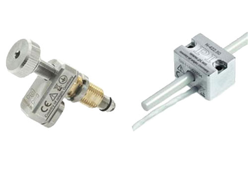
Image: Physik Instrumente (PI)
The mass budget framework
A gimbal mass budget is a line-item accounting of every component that sits on the aircraft's payload mount. For a two-axis (azimuth and elevation) stabilized gimbal carrying a daylight camera and an uncooled longwave infrared (LWIR) microbolometer, a typical breakdown looks like this:
| Component | BLDC + gearbox (g) | Piezo direct drive (g) | Savings (g) |
|---|---|---|---|
| Azimuth motor | 48 | 12 | 36 |
| Elevation motor | 38 | 10 | 28 |
| Azimuth gearbox (100:1) | 62 | 0 | 62 |
| Elevation gearbox (80:1) | 54 | 0 | 54 |
| Slip ring assembly | 28 | 28 | 0 |
| Encoders (x2) | 14 | 14 | 0 |
| Motor driver electronics | 22 | 18 | 4 |
| Cabling and connectors | 16 | 12 | 4 |
| Structural housing | 120 | 95 | 25 |
| Sensor payload (EO+IR) | 180 | 180 | 0 |
| Total | 582 | 369 | 213 |
The piezo architecture saves 213 g in this example, a 37% reduction in total gimbal mass. Two factors dominate the savings: elimination of the gearboxes (116 g) and the smaller motor mass (64 g). The housing also shrinks because the gearbox volume disappears, saving another 25 g in machined aluminum.
Mass budgets by UAV class
The savings scale with gimbal size. The following table presents representative mass budgets for three UAV classes, each comparing a BLDC geared solution against piezo direct drive.
| UAV class | MTOW range | Gimbal axes | BLDC total (g) | Piezo total (g) | Savings (g) | Savings (%) |
|---|---|---|---|---|---|---|
| Group 1 micro (sub-2 kg) | 0.5 to 2 kg | 2-axis | 285 | 168 | 117 | 41% |
| Group 1 small (2 to 9 kg) | 2 to 9 kg | 2-axis | 582 | 369 | 213 | 37% |
| Group 2 tactical (10 to 25 kg) | 10 to 25 kg | 3-axis (az/el/roll) | 1,480 | 1,020 | 460 | 31% |
| Group 3 medium (25 to 600 kg) | 25 to 600 kg | 3-axis (az/el/roll) | 3,200 | 2,350 | 850 | 27% |
As gimbal size increases, the percentage savings decrease slightly because the sensor payload (which is unchanged) becomes a larger fraction of total mass. However, the absolute savings grow substantially, and the system-level impact becomes correspondingly larger.
Group 1 micro gimbal detailed budget
For the smallest class, consider a single-sensor daylight gimbal on a sub-2 kg quad-rotor:
| Component | BLDC + gearbox (g) | Piezo direct drive (g) |
|---|---|---|
| Azimuth motor | 18 | 5 |
| Elevation motor | 14 | 4 |
| Azimuth gearbox (80:1) | 28 | 0 |
| Elevation gearbox (60:1) | 22 | 0 |
| Encoders (x2) | 6 | 6 |
| Motor driver electronics | 12 | 10 |
| Cabling | 8 | 6 |
| Structural housing | 52 | 37 |
| Camera module (1080p) | 125 | 100 |
| Total | 285 | 168 |
Note: the camera module mass differs because the lighter actuator assembly allows a more compact housing that uses a smaller camera module with an integrated lens. The piezo version uses a 16 mm lens where the BLDC version, with its larger housing, accommodates a 25 mm lens on a slightly heavier module. This is an engineering choice, not inherent to the motor.
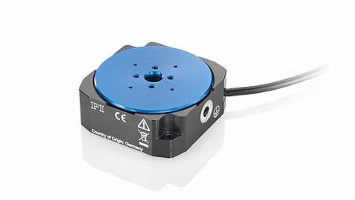
Image: Physik Instrumente (PI)
Group 2 tactical three-axis detailed budget
For a three-axis (azimuth, elevation, roll) gimbal carrying a multi-sensor suite on a 15 kg fixed-wing UAV:
| Component | BLDC + gearbox (g) | Piezo direct drive (g) |
|---|---|---|
| Azimuth motor | 120 | 35 |
| Elevation motor | 95 | 28 |
| Roll motor | 85 | 25 |
| Azimuth gearbox (120:1 harmonic) | 180 | 0 |
| Elevation gearbox (100:1 harmonic) | 150 | 0 |
| Roll gearbox (80:1 planetary) | 95 | 0 |
| Slip ring assembly | 45 | 45 |
| Encoders (x3) | 24 | 24 |
| IMU (tactical grade) | 35 | 35 |
| Motor driver electronics | 48 | 38 |
| Cabling and connectors | 28 | 20 |
| Structural housing (machined Al) | 235 | 175 |
| EO sensor (HD daylight) | 120 | 120 |
| LWIR sensor (uncooled 640x512) | 95 | 95 |
| SWIR sensor (640x512 InGaAs) | 85 | 85 |
| Optical window assembly | 40 | 40 |
| Total | 1,480 | 1,020 |
The three-axis system saves 460 g, almost entirely from gearbox elimination (425 g) and motor size reduction (212 g), offset partially by the unchanged sensor and structural content.
Why gearboxes exist in BLDC gimbal drives
Brushless DC motors excel at high-speed, low-torque operation. A typical 22 mm diameter BLDC motor used in small gimbal applications produces 8 to 15 mNm of continuous torque at 8,000 to 12,000 RPM. Gimbal axes, however, require low speed (typically under 60 deg/s slew, often under 10 deg/s for tracking) and moderate torque (0.1 to 0.5 Nm depending on payload inertia and disturbance loads). Bridging that mismatch demands a gear reduction, typically 80:1 to 150:1.
Planetary gearboxes at this scale weigh 40 to 80 g per stage and introduce backlash (1 to 3 arcminutes for precision units, 6 to 15 arcminutes for standard units). Harmonic drives reduce backlash to under 1 arcminute but cost more and still weigh 50 to 100 g at the relevant torque ratings. Either way, the gearbox adds mass, volume, a potential failure mode, and acoustic noise.
The following table summarizes the gearbox options typically considered for small gimbal applications:
| Gearbox type | Gear ratio range | Mass (g) at 0.3 Nm output | Backlash (arcmin) | Torsional stiffness (Nm/rad) | Efficiency (%) |
|---|---|---|---|---|---|
| Spur gear (2-stage) | 20:1 to 100:1 | 25 to 50 | 10 to 30 | 0.2 to 1.0 | 85 to 92 |
| Planetary (2-stage) | 25:1 to 200:1 | 40 to 80 | 1 to 6 | 0.5 to 5.0 | 80 to 90 |
| Harmonic drive | 50:1 to 200:1 | 50 to 120 | 0.3 to 1.0 | 2 to 15 | 65 to 85 |
| Cycloidal | 30:1 to 120:1 | 60 to 130 | 0.5 to 2.0 | 3 to 20 | 75 to 88 |
Harmonic drives offer the best backlash performance but at the cost of lower efficiency (which means higher power draw for the same output torque) and higher mass. Cycloidal drives are increasingly used in mid-size gimbals but remain heavier than planetary alternatives.
Gimbal Motor Technology Comparison
| Parameter | Piezoelectric | Brushless DC | Stepper |
|---|---|---|---|
| Mass per Axis(g) | 15 | 85 | 120 |
| Peak Torque(N·m) | 0.3 | 1.2 | 0.8 |
| Power (idle)(W) | 0 | 0.5 | 2 |
| Bandwidth(Hz) | 2000 | 200 | 50 |
| EMI | None | Moderate | High |
| Holding | No power | Requires power | Requires power |
Piezo motors: torque without gears
Ultrasonic piezoelectric motors generate torque through frictional coupling between a vibrating stator and a rotor. Because the driving frequency (typically 30 to 80 kHz) produces microscopic elliptical motion at the contact interface, the effective output is inherently low speed and high torque. A 20 mm diameter traveling-wave rotary piezo motor can deliver 0.1 to 0.3 Nm of holding torque and 0.05 to 0.15 Nm of continuous driving torque at speeds up to 150 RPM, matching gimbal requirements directly.
This means no gearbox is needed. The motor output shaft couples directly to the gimbal axis, either through a simple flexible coupling or a rigid flange mount. The entire gear train, its mass, its backlash, its lubrication requirements, and its acoustic signature simply disappear.
Mass comparison at component level
Consider representative components available from established manufacturers. The following comparison uses anonymized but realistic specifications from production motors in their respective size classes:
BLDC motor option A (24V, 30 mm class):
- Mass: 46 g
- Continuous torque: 10.6 mNm
- No-load speed: 11,000 RPM
- Required gearbox (53:1 planetary): 62 g
- BLDC system total per axis: 108 g
BLDC motor option B (12V, 22 mm class):
- Mass: 28 g
- Continuous torque: 6.3 mNm
- No-load speed: 14,000 RPM
- Required gearbox (100:1 planetary): 48 g
- BLDC system total per axis: 76 g
Piezo rotary motor option A (30 mm class traveling wave):
- Mass: 29 g
- Continuous torque: 0.1 Nm
- No-load speed: 150 RPM
- No gearbox required
- Piezo system total per axis: 29 g
Piezo rotary motor option B (20 mm class traveling wave):
- Mass: 12 g
- Continuous torque: 0.05 Nm
- No-load speed: 120 RPM
- No gearbox required
- Piezo system total per axis: 12 g
Piezo rotary motor option C (40 mm class standing wave):
- Mass: 48 g
- Continuous torque: 0.25 Nm
- No-load speed: 80 RPM
- No gearbox required
- Piezo system total per axis: 48 g
The comparison for the same torque output class (0.1 Nm continuous at the gimbal axis):
| Configuration | Mass per axis (g) | Output torque (Nm) | Max speed (deg/s) |
|---|---|---|---|
| BLDC option A + 53:1 gearbox | 108 | 0.56 (max) | 1,245 |
| BLDC option B + 100:1 gearbox | 76 | 0.63 (max) | 840 |
| Piezo option A (30 mm) | 29 | 0.10 (continuous) | 900 |
| Piezo option B (20 mm) | 12 | 0.05 (continuous) | 720 |
| Piezo option C (40 mm) | 48 | 0.25 (continuous) | 480 |
Even accounting for the BLDC solutions having higher peak torque capability, the piezo motors deliver adequate torque for gimbal tracking at 60 to 75% less mass per axis. For the smallest gimbal applications, piezo option B at 12 g per axis is particularly compelling: it weighs less than many gearboxes alone.
Power consumption: the second trade
Mass savings alone would justify attention, but the power story reinforces the case. Small UAVs operate from battery packs with limited energy density (typically 180 to 250 Wh/kg for lithium polymer cells). Every watt consumed by the gimbal is a watt unavailable for propulsion.
Power consumption comparison table
The following table compares power draw across operating modes for representative two-axis gimbals in the same size class:
| Operating mode | BLDC + planetary (W) | BLDC + harmonic (W) | Piezo direct drive (W) |
|---|---|---|---|
| Idle (holding position) | 0.8 to 1.5 | 0.5 to 1.2 | 0.0 |
| Slow tracking (5 deg/s) | 2.0 to 4.0 | 1.8 to 3.5 | 0.5 to 1.5 |
| Active surveillance scanning (30 deg/s) | 3.5 to 6.0 | 3.0 to 5.5 | 1.5 to 3.0 |
| Rapid slew (100 deg/s) | 8.0 to 15.0 | 7.0 to 12.0 | 3.0 to 6.0 |
| Maximum slew (200 deg/s) | 12.0 to 20.0 | 10.0 to 18.0 | 4.0 to 8.0 |
| Weighted mission average* | 4.5 to 7.5 | 3.8 to 6.5 | 1.2 to 2.8 |
*Weighted mission average assumes a typical surveillance profile: 50% slow tracking, 30% active scanning, 10% idle, 8% rapid slew, 2% max slew.
BLDC gimbal power draw
A BLDC motor driving through a gearbox draws current proportional to the output torque divided by the gear ratio and motor torque constant. In a gimbal tracking scenario (slow, continuous motion with frequent direction changes), the motor spends significant time accelerating and decelerating the reflected inertia of the gearbox. Typical power consumption for a two-axis BLDC gimbal in active tracking mode ranges from 3 to 8 W, with peaks of 12 to 15 W during rapid slew maneuvers.
At idle (holding position), the BLDC system consumes 0.5 to 1.5 W because the motor must remain energized to resist disturbance torques, as the gearbox backdrive friction alone is insufficient for precision pointing.
Piezo gimbal power draw
Piezoelectric motors have a fundamentally different power profile. When not moving, they consume zero electrical power. The friction-based coupling that enables torque generation also provides inherent self-locking: the rotor cannot be back-driven by external torques below the holding torque threshold. This is a critical advantage for battery-powered systems.
During active tracking, a two-axis piezo gimbal typically draws 1 to 3 W. During maximum slew, power peaks at 4 to 8 W. The average power consumption over a typical surveillance mission profile (80% tracking, 15% scanning, 5% rapid slew) is roughly 40 to 60% lower than the BLDC equivalent.
Energy budget worked example
For a 4-hour surveillance mission on a small quad-rotor UAV with a 100 Wh battery pack:
BLDC gimbal energy consumption:
- Weighted average power: 5.5 W
- Mission energy: 5.5 W x 4 h = 22.0 Wh
- Fraction of battery: 22.0%
Piezo gimbal energy consumption:
- Weighted average power: 2.0 W
- Mission energy: 2.0 W x 4 h = 8.0 Wh
- Fraction of battery: 8.0%
Energy savings: 14.0 Wh (64% reduction in gimbal energy)
At a lithium polymer energy density of 200 Wh/kg, the 14.0 Wh savings is equivalent to 70 g of battery mass. This mass can either be removed (reducing vehicle weight) or retained (extending flight time by approximately 14% from the gimbal power savings alone, since the gimbal's share of total power is modest relative to propulsion).
The zero-idle-power characteristic of piezo motors is particularly valuable for loiter missions. A UAV orbiting a target area with the gimbal tracking at low rate spends 50 to 70% of the time with the gimbal essentially stationary or moving at under 2 deg/s. During those periods, the BLDC system still draws 0.8 to 1.5 W for holding torque, while the piezo system draws effectively zero.
Structural mass cascade
Mass savings in actuators produce secondary savings in supporting structure. This cascade effect is well understood in aerospace engineering, where the "mass multiplication factor" for airborne systems typically ranges from 2.5 to 4.0. That is, for every gram saved on a payload component, 2.5 to 4.0 grams can be saved from the overall vehicle because the airframe, propulsion system, and battery can all be downsized.
For a small UAV gimbal, the cascade is more modest because the gimbal is a small fraction of total vehicle mass. A reasonable multiplication factor is 1.5 to 2.0. The 213 g of direct gimbal mass savings from the Group 1 small example therefore enables 320 to 426 g of total vehicle mass reduction, or equivalently, that mass budget can be reallocated.
Cascade factor derivation
The cascade factor depends on the vehicle's mass breakdown. Consider a 5 kg quad-rotor UAV:
| Component | Mass (g) | Fraction (%) |
|---|---|---|
| Airframe (including landing gear) | 1,200 | 24.0% |
| Propulsion (4 motors, ESCs, props) | 600 | 12.0% |
| Battery (4S 5000 mAh LiPo) | 550 | 11.0% |
| Flight controller and avionics | 150 | 3.0% |
| Communication system | 120 | 2.4% |
| Gimbal (BLDC version) | 582 | 11.6% |
| Payload margin / accessories | 1,798 | 36.0% |
| Total | 5,000 | 100% |
If the gimbal mass drops by 213 g, and the vehicle is resized to maintain the same thrust-to-weight ratio:
- Battery can shrink proportionally: 213 g / 5000 g x 550 g = 23 g saved
- Propulsion can downsize slightly: 213 g / 5000 g x 600 g = 26 g saved
- Airframe can be lighter: 213 g / 5000 g x 1200 g = 51 g saved
- Direct gimbal savings: 213 g
Total cascade savings: 213 + 23 + 26 + 51 = 313 g
Cascade factor: 313 / 213 = 1.47
For vehicles where the gimbal represents a larger fraction of total mass (such as micro-UAVs under 2 kg), the cascade factor increases toward 1.8 to 2.0 because the gimbal savings have a proportionally larger impact on the overall vehicle sizing.
What you can do with 200+ grams
In the context of a 2 to 5 kg class UAV, 200 g of freed payload mass opens real options:
- Upgrade from uncooled to cooled IR detector: A miniature Stirling cooler for a 640x512 LWIR detector adds approximately 150 to 200 g. Moving from uncooled (NETD of 50 mK) to cooled (NETD of 20 mK) detection dramatically improves thermal sensitivity and extends detection range by a factor of 1.5 to 2.
- Add a laser rangefinder module: Compact eye-safe laser rangefinder modules weigh 80 to 150 g and provide target geolocation accuracy of 1 to 5 m at ranges up to 3 km.
- Increase battery capacity: 200 g of additional lithium polymer cells adds approximately 36 to 50 Wh, extending endurance by 15 to 25% on a typical small quad-rotor.
- Larger optical aperture: Stepping from a 25 mm to a 35 mm daylight camera lens improves diffraction-limited resolution by 40%, directly translating to longer identification range.
- Add a laser designator: Compact 1064 nm laser designators weigh 100 to 180 g and enable guided munition cueing from the same platform that performs ISR.
These are not theoretical trade-offs. They represent the actual decisions that gimbal system integrators make when selecting actuator technology.
Inertia and bandwidth implications
Beyond static mass, the rotational inertia of the actuator assembly affects control bandwidth. A gearbox, while reducing reflected load inertia at the motor by the square of the gear ratio, adds its own rotor inertia. More importantly, gearbox compliance (torsional stiffness on the order of 1 to 10 Nm/rad for miniature planetary units) introduces a resonant mode that limits achievable servo bandwidth.
A typical BLDC + planetary gearbox gimbal axis achieves a closed-loop control bandwidth of 15 to 40 Hz, limited by the structural resonance of the gear train. Piezo direct-drive systems, with no intermediate compliance, can achieve 80 to 200 Hz bandwidth, depending on the drive electronics and sensor feedback rate. This higher bandwidth directly translates to better disturbance rejection (critical for vibration-rich UAV platforms) and tighter line-of-sight stabilization.
Calculating the gearbox resonance limit
The torsional resonance of a motor-gearbox-load system can be estimated as:
f_res = (1 / 2pi) x sqrt(k_gb / J_eq)
where k_gb is the gearbox torsional stiffness (Nm/rad) and J_eq is the equivalent inertia at the output (kgm^2).
For a representative system:
- k_gb = 2 Nm/rad (typical 22 mm planetary gearbox)
- J_load = 0.0005 kgm^2 (gimbal elevation axis payload inertia)
- J_motor_reflected = J_motor x N^2 = 5e-7 x 100^2 = 0.005 kgm^2 (often negligible at the output side for high-ratio gearboxes, but the gearbox internal inertia adds approximately 0.0002 kgm^2)
- J_eq = J_load + J_gearbox_internal = 0.0005 + 0.0002 = 0.0007 kgm^2
f_res = (1 / 2pi) x sqrt(2 / 0.0007) = (1 / 6.283) x sqrt(2857) = (1 / 6.283) x 53.5 = 8.5 Hz
Wait: that seems low. Let us recalculate more carefully. The torsional stiffness of 2 Nm/rad is at the output. For a 22 mm HP gearbox, the rated stiffness is closer to 4 Nm/rad:
f_res = (1 / 2pi) x sqrt(4 / 0.0007) = (1 / 6.283) x sqrt(5714) = (1 / 6.283) x 75.6 = 12.0 Hz
With a higher-quality 32 mm harmonic drive at k_gb = 15 Nm/rad:
f_res = (1 / 2pi) x sqrt(15 / 0.0007) = (1 / 6.283) x sqrt(21,429) = (1 / 6.283) x 146 = 23.3 Hz
The servo bandwidth must be set below approximately 1/3 to 1/2 of this resonance to maintain adequate phase margin. So for the planetary case, maximum bandwidth is approximately 4 to 6 Hz; for the harmonic drive case, approximately 8 to 12 Hz. In practice, additional controller techniques (notch filters, feedforward) can push bandwidth higher, to the 15 to 40 Hz range for planetary and 30 to 60 Hz for harmonic drives.
For the piezo direct-drive case, the first structural resonance is between the motor and the gimbal payload, with no intermediate compliance. The stiffness is determined by the motor mounting flange and the gimbal structure, typically 100 to 500 Nm/rad. Using the same load inertia:
f_res_piezo = (1 / 2pi) x sqrt(200 / 0.0007) = (1 / 6.283) x sqrt(285,714) = (1 / 6.283) x 534.5 = 85.1 Hz
This places the structural resonance at 85 Hz, allowing servo bandwidths of 30 to 40 Hz at a minimum and, with proper controller design, 80 to 200 Hz. The bandwidth advantage is directly attributable to the elimination of the gearbox compliance.
Practical constraints and honest trade-offs
Piezo motors are not universally superior. Several factors constrain their applicability:
Speed limitations
Ultrasonic motors are inherently slow. A 30 mm class rotary piezo motor tops out at 100 to 200 RPM (roughly 600 to 1,200 deg/s). For gimbal applications requiring slew rates under 200 deg/s, this is more than adequate. For applications demanding rapid repointing (such as electronic warfare antenna positioners requiring 1,000+ deg/s), BLDC motors remain the better choice.
Wear
The frictional contact mechanism means piezo motors have finite life that depends on load, speed, and environmental conditions. Typical rated life for quality ultrasonic motors is 3,000 to 10,000 hours under rated conditions. For a surveillance gimbal operating 4 to 8 hours per day, this translates to 1 to 7 years of service life, generally acceptable for military and commercial UAV programs that plan periodic overhaul cycles.
| Operating condition | Expected motor life (hours) |
|---|---|
| Light load (< 20% rated torque), low duty cycle | 8,000 to 12,000 |
| Moderate load (20 to 50% rated torque), typical surveillance | 5,000 to 8,000 |
| Heavy load (50 to 80% rated torque), continuous scanning | 3,000 to 5,000 |
| Near rated torque, high duty cycle | 1,500 to 3,000 |
Temperature sensitivity
Piezoelectric materials exhibit temperature-dependent performance. Torque output and efficiency both degrade at temperature extremes, and the Curie temperature of the piezoceramic sets an absolute operating limit (typically 150 to 300 C for PZT-based materials, well above normal operating range). At low temperatures (below -20 C), the piezoceramic stiffens and the friction interface behavior changes, typically reducing torque output by 15 to 30%. At high temperatures (above 60 C), the dielectric losses increase, reducing efficiency. This topic is covered in detail in the companion article on altitude and temperature operation.
Cost
Precision piezoelectric motors remain more expensive per unit than equivalent BLDC motors, typically by a factor of 2 to 5. However, the elimination of the gearbox partially offsets this at the system level. Total actuator subsystem cost (motor + gearbox + coupling + assembly labor) is often comparable or only 20 to 40% higher for the piezo solution.
| Cost element | BLDC + gearbox | Piezo direct drive |
|---|---|---|
| Motor unit cost | $30 to $80 | $80 to $250 |
| Gearbox unit cost | $60 to $200 | $0 |
| Coupling / adapter | $10 to $30 | $5 to $15 |
| Assembly labor (per axis) | 45 to 90 min | 15 to 30 min |
| Total per axis (production) | $130 to $400 | $100 to $280 |
The assembly labor savings are significant and often overlooked. Aligning a motor, gearbox, and encoder stack requires careful mechanical adjustment to minimize backlash and ensure concentricity. The piezo direct-drive assembly, with its single motor bolted to the gimbal frame, is substantially simpler.
Worked example 1: retrofitting a commercial gimbal (Group 2)
Consider a commercially available two-axis gimbal designed for Group 2 UAVs (10 to 25 kg MTOW). The original configuration uses BLDC motors with harmonic drive reducers:
Original specification:
- Total gimbal mass: 1,350 g
- Actuator subsystem mass: 480 g (2 motors at 85 g, 2 harmonic drives at 120 g, encoders, cabling)
- Sensor payload: 540 g (HD daylight + uncooled IR)
- Control bandwidth: 25 Hz (-3 dB)
- Power consumption: 6 W average, 18 W peak
- Stabilization performance: 80 urad RMS jitter in moderate turbulence
Retrofit with piezo direct drive:
- Total gimbal mass: 1,020 g (24% reduction)
- Actuator subsystem mass: 150 g (2 piezo motors at 45 g, encoders, cabling)
- Sensor payload: 540 g (unchanged) or upgradeable to 870 g within original mass envelope
- Control bandwidth: 120 Hz (-3 dB)
- Power consumption: 2.5 W average, 9 W peak
- Stabilization performance: 25 urad RMS jitter in moderate turbulence (improved by 3.2x due to higher bandwidth)
The freed 330 g of actuator mass can be used to upgrade the IR sensor from uncooled 640x512 to a cooled 640x512 detector with a miniature Stirling cooler, transforming the gimbal from a short-range observation tool into a medium-range detection and tracking system.
Detection range impact calculation:
Using the Johnson criteria for target detection (1.5 line pairs across the target minimum dimension) with a 50 mm, f/2.0 LWIR lens:
- Uncooled detector (NETD 50 mK, 17 um pitch): MRTD at 1 cycle/mrad = 120 mK. Detection range for a 2.3 m vehicle-sized target (delta-T = 4 K above background): approximately 4.2 km.
- Cooled detector (NETD 20 mK, 15 um pitch): MRTD at 1 cycle/mrad = 35 mK. Detection range for same target: approximately 7.8 km.
The detection range nearly doubles, representing a qualitative upgrade in mission capability enabled purely by the mass savings from the actuator change.
Worked example 2: designing a micro-gimbal for a sub-2 kg UAV
For Group 1 micro-UAVs, the mass budget is brutally tight. Consider designing a single-axis (elevation only, with UAV yaw for azimuth) gimbal for a 1.2 kg quad-rotor surveillance drone:
Requirements:
- Total gimbal mass budget: 120 g maximum
- Sensor: 1080p daylight camera, 25 mm lens, 85 g
- Elevation range: -90 to +10 degrees
- Slew rate: 60 deg/s maximum
- Stabilization: 200 urad RMS (sufficient for 1080p at 25 mm focal length)
BLDC + gearbox attempt:
- Motor (15 mm BLDC): 12 g
- Gearbox (60:1 planetary): 18 g
- Encoder: 3 g
- Driver electronics: 8 g
- Housing and mount: 22 g
- Camera: 85 g
- Total: 148 g. Exceeds budget by 28 g.
To meet the budget, the camera must be downgraded to a lighter module (60 g), which means a smaller lens (16 mm) and reduced detection range.
Piezo direct drive:
- Motor (15 mm traveling wave): 5 g
- Encoder: 3 g
- Driver electronics: 7 g
- Housing and mount: 16 g
- Camera: 85 g
- Total: 116 g. Within budget with 4 g margin.
The piezo solution meets the mass budget with the full 25 mm lens camera, while the BLDC solution requires a compromised sensor. This example illustrates how piezo motors enable capabilities that are simply not achievable with geared drives at the smallest UAV scales.
Worked example 3: three-axis gimbal for a Group 3 fixed-wing ISR platform
For larger platforms, the analysis shifts from "can we fit it?" to "what additional capability does the mass savings buy?"
Platform: 80 kg fixed-wing UAV, 20 hour endurance Gimbal requirement: 3-axis stabilized, multi-sensor (EO/MWIR/laser rangefinder)
| Component | BLDC + harmonic (g) | Piezo direct drive (g) |
|---|---|---|
| Azimuth motor + gearbox | 420 | 95 |
| Elevation motor + gearbox | 380 | 85 |
| Roll motor + gearbox | 310 | 70 |
| Encoders (x3) | 45 | 45 |
| IMU (navigation grade) | 65 | 65 |
| Driver electronics | 85 | 65 |
| Cabling and slip rings | 60 | 45 |
| Structure and housing | 520 | 390 |
| EO sensor (4K, 150 mm lens) | 280 | 280 |
| MWIR sensor (cooled, 640x512) | 350 | 350 |
| Laser rangefinder | 140 | 140 |
| Optical windows | 95 | 95 |
| Total | 2,750 | 1,725 |
Mass savings: 1,025 g (37%)
With 1 kg of freed mass on an 80 kg platform, the cascade factor (approximately 1.3 for a large fixed-wing) yields 1,330 g of system-level savings. This can be reallocated to:
- Additional fuel: 1,330 g of JP-8 at 12,000 Wh/kg adds approximately 2.5 hours of endurance (from 20 to 22.5 hours), a 12% increase.
- Alternatively, a second gimbal for simultaneous wide-area surveillance and narrow-field tracking.
The power savings are also meaningful on long-endurance platforms. Over a 20-hour mission, the piezo gimbal saves approximately (5.0 - 1.8) W x 20 h = 64 Wh compared to the BLDC version. For an electrically powered UAV, this is equivalent to 320 g of battery mass; for a fuel-burning platform with a generator, it reduces generator load and extends engine life.
System-level mass budgeting methodology
For engineers conducting their own gimbal mass trades, the following methodology provides a structured approach:
- Define the mission requirements: slew rate, stabilization accuracy, sensor FOV, detection range, endurance.
- Size the sensor payload to meet detection range and FOV requirements. This establishes the minimum sensor mass.
- Calculate disturbance torques from aerodynamic loads, vibration, and cable drag. This sets the minimum actuator torque.
- Select candidate actuators (BLDC+gearbox vs. piezo direct drive) that meet the torque requirement.
- Build the mass budget line by line, including all mounting hardware, cabling, and thermal management.
- Apply the cascade factor (1.3 to 2.0, depending on UAV size class) to translate gimbal mass differences into vehicle-level impacts.
- Evaluate the freed mass: what mission capability improvement does the lighter actuator enable?
- Conduct the power trade: calculate mission energy consumption for each actuator option and convert the difference to equivalent mass or endurance.
- Assess lifetime cost: include motor replacement intervals, assembly complexity, and spares inventory.
This trade study should be performed early in the design cycle, before structural layouts are frozen. The volume savings from eliminating gearboxes often enable more compact gimbal geometries that further reduce drag and improve aircraft integration.
Disturbance torque estimation
For step 3, the dominant disturbance torques on a gimbal axis are:
| Torque source | Typical magnitude | Calculation method |
|---|---|---|
| Aerodynamic drag | 0.01 to 0.1 Nm | T = 0.5 x rho x v^2 x Cd x A x r, where r is the moment arm from the axis to the center of pressure |
| Cable/harness restoring torque | 0.005 to 0.05 Nm | Measured empirically; depends on cable routing and flexibility |
| Vibration-induced inertial torque | 0.01 to 0.2 Nm | T = J x alpha, where alpha is the angular acceleration at the mount point |
| Gravity unbalance | 0 to 0.1 Nm | T = m x g x d, where d is the CG offset from the rotation axis |
| Bearing/friction torque | 0.002 to 0.02 Nm | Depends on bearing type and preload |
The actuator must provide at least 2x the sum of these disturbance torques to maintain adequate servo margin. For a typical small gimbal, the total disturbance torque budget is 0.03 to 0.3 Nm, well within the range of 20 to 30 mm piezo rotary motors.
Conclusion
The mass budget case for piezoelectric direct-drive gimbal actuators is straightforward: they save 100 to 1,000 g per gimbal compared to BLDC + gearbox solutions, depending on the size class. That mass, multiplied by the system cascade factor, translates into meaningful capability upgrades or endurance improvements. The power savings (40 to 60% lower average consumption) add further value for battery-constrained platforms.
These advantages come with known constraints around speed, wear, and cost. For gimbal applications on small to medium UAVs, where slew rates rarely exceed 200 deg/s and operating hours per mission are measured in single digits, those constraints are manageable. The trade space, when honestly evaluated with real numbers, favors piezo direct drive for the majority of stabilized payload applications in this class.
The tables and worked examples in this article provide a starting framework for system-level mass trades. The specific numbers will vary with each application, but the methodology is consistent: build the budget line by line, apply the cascade, and evaluate what the freed mass enables. In nearly every case where the gimbal fits the piezo motor's torque and speed envelope, the mass trade closes in favor of direct drive.