技术对比
Technology selection framework: five questions that determine your motor choice
A structured decision process with specific thresholds for choosing between piezo, servo, stepper, and voice coil actuators
Technology Selection Framework: Five Questions That Determine Your Motor Choice
Engineers waste months evaluating actuator technologies for precision motion systems. The process typically begins with a catalog search, proceeds through vendor demos, and ends with a decision shaped as much by which sales engineer followed up most persistently as by technical merit. The result is often a system that works but was never the best choice, or one that fails on a single parameter that should have been identified in the first week.
Most actuator decisions can be resolved by answering five questions in sequence. Each question carries specific numerical thresholds that narrow the candidate field. By the third question, you will typically have eliminated two or three technologies entirely. By the fifth, you will have one clear winner or two candidates requiring a focused trade study.
This framework covers the six architectures most commonly encountered in precision positioning: stepper motors with lead screws, servo motors with ball screws, direct-drive linear motors, ultrasonic piezoelectric motors, voice coil actuators, and piezo stack/flexure actuators. For head-to-head comparisons, see piezo versus servo, piezo versus stepper, and piezo versus voice coil.
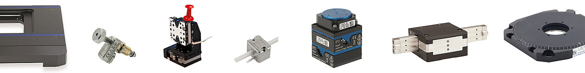 A selection of piezo motor stages spanning the technology range: miniature ultrasonic linear stages, stick-slip positioners, NEXACT walking-drive stages, and voice coil tip-tilt platforms. Each form factor targets a different region of the resolution-speed-force design space. Source: PI
The Five Questions
The questions are ordered by discriminating power. Resolution eliminates more candidates than speed, speed eliminates more than force, and so on. Answer them in order.
- What resolution do you actually need?
- What speed and stroke are required?
- What force do you need?
- What is the operating environment?
- What is the duty cycle and thermal budget?
The goal is elimination, not optimization. You are looking for reasons to remove a technology from consideration, not reasons to select one.
Technology Comparison Matrix
| 参数 | Piezo | 步进 | 伺服 | 音圈 |
|---|---|---|---|---|
| 分辨率 | 最优 | 良好 | 良好 | 良好 |
| 速度 | 良好 | 最优 | 最优 | 有限 |
| 推力 | 有限 | 良好 | 最优 | 良好 |
| 真空 | 最优 | 差 | 一般 | 良好 |
| 成本 | 高 | 低 | 中 | 中 |
| 尺寸 | 最优 | Large | Large | Compact |
Question 1: What Resolution Do You Actually Need?
Resolution, defined as the minimum incremental motion (MIM) that the system can reliably execute in both directions under load, is the single most powerful discriminator. Be precise about this number, and be honest. Specifying 10 nm resolution when your process tolerance is 1 micrometer wastes money and adds mechanical risk. Conversely, specifying 1 micrometer when you actually need 50 nm leads to painful retrofits later.
Resolution is not encoder resolution. It is the smallest reliable position change at the workpiece, measured bidirectionally, under the actual operating load. A 1 nm encoder reading means nothing if the ball screw has 3 micrometers of backlash.
Resolution Tier 1: Greater Than 10 Micrometers
All technologies are viable. Stepper motors are the default for cost reasons. A NEMA 17 stepper with a 2 mm pitch lead screw and 1/16 microstepping delivers approximately 6 micrometer theoretical step size, which translates to roughly 10 to 20 micrometer actual MIM after accounting for friction and resonance effects. Total axis cost runs $50 to $300 for the motor, driver, and mechanical components.
Products: Oriental Motor PKP Series (0.9 degree step, $80), Thorlabs DRV014 motorized actuator (29 nm encoder resolution, but ~10 um practical MIM with lead screw), any standard NEMA 17/23 stepper with lead screw.
Recommendation: Stepper motor. Servo motor if you also need high speed. Do not use piezo at this resolution tier unless environmental constraints (Question 4) force it.
Resolution Tier 2: 1 to 10 Micrometers
Steppers with fine microstepping and precision lead screws can reach this range, but reliability degrades below 5 micrometers due to low-frequency resonance and the nonlinear torque profile of microstepping. Servo motors with ball screws and rotary encoders are reliable throughout this range. Voice coil actuators with linear encoders handle short strokes well. Piezo motors are viable but typically unnecessary at this cost.
Adding a closed-loop encoder to a stepper system improves reliability in this range substantially. The Trinamic TMC5160 driver with an external encoder achieves reliable 2 micrometer positioning with a standard stepper and lead screw.
Products: Newport ILS250CC (servo, 100 nm encoder resolution, practical MIM 0.5 to 1 um over 250 mm travel), PI M-230 (DC servo with ball screw, 50 nm resolution over 25 mm), Thorlabs Z812B (stepper, 29 nm encoder resolution, practical MIM ~1 um for 12 mm travel).
Recommendation: Servo with ball screw for strokes above 50 mm. Stepper with closed-loop encoder if cost is paramount. Do not over-engineer this tier.
Resolution Tier 3: 100 Nanometers to 1 Micrometer
Steppers are eliminated. Their mechanical transmission errors (lead screw pitch variation, backlash, resonance-induced position uncertainty) exceed this resolution floor regardless of encoder quality. The remaining candidates are servo motors with either direct-drive linear architecture or ball screw with external linear encoder, voice coil actuators with linear encoders, and piezo motors.
This is where technology selection begins to matter. A servo with precision ball screw and linear encoder can deliver 100 nm resolution, but the system requires backlash management, thermal compensation, and high-quality guiding. A piezo motor delivers the same resolution from a simpler package with no backlash by design.
Products: PI U-521 PILine (ultrasonic piezo, 1 nm encoder resolution, practical MIM ~50 nm over 18 mm travel, 200 mm/s), Aerotech ANT95-L (direct-drive servo, 100 nm resolution over 50 to 400 mm), SmarAct SLC-2430 (stick-slip piezo, 1 nm closed-loop resolution over 31 mm travel), Newport XMS160 (linear servo, 100 nm MIM).
Recommendation: Piezo motor for strokes below 100 mm and speeds below 50 mm/s. Direct-drive linear servo for longer strokes or higher speeds. Voice coil for strokes below 5 mm with constant-force requirements.
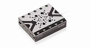 PI N-565 NEXACT: sub-nanometer resolution over 30 mm travel. At this resolution tier, piezo motors compete directly with servo linear stages but in a fraction of the size and with zero-power holding. Source: PI
Resolution Tier 4: 1 to 100 Nanometers
Three architectures remain: piezo motors with high-resolution encoders, piezo stack actuators in flexure stages with capacitive or interferometric sensors, and voice coil actuators with capacitive feedback for strokes below approximately 1 mm.
Direct-drive linear servos can reach this range over long strokes, but they require air bearings, interferometric feedback, and vibration-isolated granite structures. System cost often exceeds $50,000 per axis.
Piezo motors in this tier use optical or capacitive encoders with sub-nanometer interpolation. The PI N-664 NEXACT achieves 0.03 nm open-loop resolution. The SmarAct SLC-1720 provides 1 nm closed-loop resolution in a 12 mm travel package.
Products: PI N-664 NEXACT (0.03 nm open-loop resolution), SmarAct SLC-1720 (1 nm CL, 12 mm travel), PI P-752 LISA (piezo flexure, 1 nm CL, 25 um stroke), Aerotech QNP-XY (piezo flexure, 0.15 nm resolution, 100 um stroke), H2W NCC02-15-020-1X voice coil (sub-100 nm with capacitive feedback, 1 mm stroke).
Recommendation: Piezo motor for travel above 1 mm. Piezo flexure for travel below 500 micrometers with maximum stability. Voice coil only for sub-mm stroke with strictly constant-force profiles.
Resolution Tier 5: Below 1 Nanometer
Piezo stack actuators with capacitive sensors in flexure stages. This is the only commercially viable solution for sub-nanometer closed-loop positioning. The PI P-625 PIFOC achieves 0.1 nm resolution over 400 micrometer travel with a capacitive sensor. The Aerotech QNP series achieves 0.15 nm resolution over 100 micrometer travel.
At this level, everything matters: amplifier noise, cable shielding, thermal stability of the stage material, vibration isolation, and even the acoustic environment. The actuator is often the easiest part; the system around it determines whether the specification is achieved.
Products: PI P-625.1CD (0.1 nm, 400 um travel), Aerotech QNP-100Z (0.15 nm, 100 um travel), PI P-363 PicoCube (0.1 nm, 5 um travel), nPoint NPXY100Z (0.1 nm, 100 um travel).
Recommendation: Piezo flexure, period. If you need sub-nanometer resolution over more than 1 mm of travel, you need a multi-stage architecture.
Question 2: What Speed and Stroke Are Required?
Speed and stroke together define the motion envelope. Some technologies dominate at high speed with long stroke. Others dominate at low speed with short stroke. The overlap zone in the middle is where most selection debates occur.
When specifying speed, distinguish between maximum slew velocity (peak speed during repositioning), scanning velocity (constant speed during the working process), and settling time (time to reach and stabilize at target). An actuator that slews at 500 mm/s but takes 200 ms to settle is slower in practice than one that slews at 100 mm/s and settles in 5 ms, if the application involves many short moves.
Speed Thresholds
Above 500 mm/s: This eliminates all piezo motors except specialized designs like the Xeryon XLS, which reaches 1,000 mm/s by using a ceramic plate resonator that sacrifices force density for velocity. For sustained motion above 500 mm/s, servo motors (either rotary with ball screw or direct-drive linear) are the only practical option. The Aerotech BLMX series reaches 5 m/s with peak force of 4,252 N. The Parker MX80L handles 2,000 mm/s. Stepper motors technically reach this speed range but lose 50% to 80% of their low-speed torque, making them unreliable.
50 to 500 mm/s: Servo motors are the default. Direct-drive linear servos (PI V-551, Aerotech ABL1500) handle this range with precision. Some ultrasonic piezo motors operate here: the PI PILine U-521 reaches 200 mm/s, and traveling-wave rotary types driving a fine-pitch screw can sustain 100 to 200 mm/s. Voice coil actuators reach this range for short strokes (below 10 mm). Steppers are limited by torque falloff.
1 to 50 mm/s: The sweet spot for ultrasonic piezo motors. All technologies are viable here, so resolution, environment, and force become the discriminators. The SmarAct SLC-2430 handles over 20 mm/s. The PI N-310 NEXACT operates up to 10 mm/s with sub-nanometer resolution.
Below 1 mm/s: Slow, ultra-precise positioning. Stepper motors struggle due to low-frequency resonance (the resonant speed for a typical stepper/lead screw combination falls between 0.4 and 2 mm/s, exactly in this range). Servo motors work but draw full power at near-stall conditions, generating heat that degrades metrology accuracy. Piezo motors and piezo stacks excel: smooth motion, zero power at hold, no resonance artifacts.
Stroke Thresholds
Stroke interacts with speed to further narrow the field. This interaction is detailed in the load-stroke-resolution tradeoffs article.
Below 1 mm: Piezo stack actuators with flexure amplification. A 10 mm PZT stack produces approximately 10 to 15 micrometers of native stroke. With 10:1 lever amplification (such as the Cedrat APA series), stroke reaches 150 micrometers to 1 mm. Voice coil actuators also work for sub-mm strokes. Servo and stepper motors are mechanically impractical at this scale.
1 to 50 mm: The natural range for piezo motors and voice coils. The PI PILine U-521 covers 18 mm. The SmarAct SLC-2430 covers 31 mm. Voice coils from BEI Kimco and H2W Technologies cover 1 to 25 mm strokes. Servo motors with short ball screws work but carry unnecessary mechanical overhead.
50 to 500 mm: Servo motors with ball screws or direct-drive linear motors. Piezo motors are available at these strokes (the PI PILine N-381 covers 306 mm), but speed is limited. Voice coils are impractical above 50 mm because the magnet assembly length and heat generation become prohibitive.
Above 500 mm: Servo motors with ball screws or roller screws. Direct-drive linear motors for high-precision applications. The Aerotech PRO-LM series covers strokes to 2 meters. No other technology is practical at this scale unless a multi-stage architecture is used.
Settling Time
If your application is dominated by move-settle cycles rather than continuous scanning, settling time may matter more than peak velocity:
- Piezo stacks: 0.5 to 5 ms (high resonance frequency, typically 1 to 50 kHz)
- Voice coils: 1 to 10 ms for short strokes
- Piezo motors: 2 to 20 ms, depending on stroke and controller tuning
- Servo motors: 5 to 50 ms with optimized PID control
- Stepper motors: 10 to 100 ms due to step-induced ringing
If sub-millisecond settling is required, piezo stack actuators in flexure stages are the only viable option.
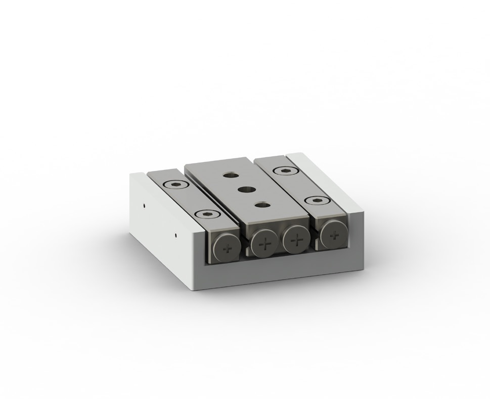 SmarAct SLC-2430 stick-slip positioner: 31 mm travel, sub-nanometer closed-loop resolution, and zero-power holding in a package smaller than a postage stamp. A servo-ballscrew stage with comparable travel would be 10 to 20 times larger and heavier. Source: SmarAct
Question 3: What Force Do You Need?
Force requirements eliminate technologies less frequently than resolution and speed, but they can be decisive at the extremes.
Distinguish between continuous force (sustained indefinitely during operation), peak force (maximum during acceleration or disturbance rejection), and holding force (maintaining position at rest). The distinction between continuous and holding force is critical because some technologies hold position with zero power while others require full stall current.
Force Thresholds
Below 10 N continuous: All technologies are viable. This is the common range for precision positioning, fiber alignment, optical component adjustment, and similar applications. Selection depends entirely on resolution, speed, stroke, and environment. Voice coils deliver exceptionally clean, constant force across the full stroke. Piezo motors deliver this force from compact packages with zero-power hold.
10 to 100 N continuous: Servo motors with screw drives are the default. Amplified piezo actuators enter consideration: the Cedrat APA60SL produces 390 N of blocking force from a 60 mm package, with 52 micrometer stroke. The Cedrat APA60ML generates 3,300 N blocking force. Piezo motors with multiple contact points or stacked configurations handle 10 to 50 N. Voice coil actuators can reach this range but generate substantial I^2*R heating; the H2W NCC05-18-060-2X produces 60 N continuous.
100 to 1,000 N continuous: Servo motors dominate. Ball screw or roller screw transmissions convert motor torque efficiently. A NEMA 34 servo with a 10 mm pitch roller screw delivers 2,000 to 5,000 N. Voice coils exist at this level for specialized applications; the H2W NCC08-30-100-2X delivers up to 4,000 N peak force, though continuous force is lower due to thermal limits. Piezo motors are generally not competitive here, except for the PI N-216 NEXLINE, which produces 600 N holding force through a walking piezo mechanism.
Above 1,000 N continuous: Servo motors with roller screws, or direct-drive linear motors for high-speed applications. The Aerotech BLMX series delivers 4,252 N peak force. For static or quasi-static force generation, PICA Power piezoelectric stacks from PI produce up to 70,000 N of blocking force from monolithic ceramic stacks. These are not motors; they are solid-state actuators with strokes measured in micrometers, but they deliver extraordinary force density for applications like clamping, pressing, and preloading.
Holding Force: A Critical Distinction
Holding force at zero speed separates technologies sharply and links directly to Question 5 (duty cycle and thermal budget):
- Stepper motors: Provide holding torque from detent torque alone (roughly 5% to 10% of rated holding torque) at zero power, or full holding torque at rated current. Most applications energize the motor during hold, consuming 1 to 5 W.
- Servo motors: Require continuous current for any holding force. Power consumption follows I^2 * R, and thermal management is required for extended hold periods. A servo holding 50 N through a ball screw may dissipate 10 to 30 W as heat.
- Voice coils: Same as servo. Continuous current and heat generation for any static force. No detent force, no passive hold.
- Piezo motors: Full holding force at zero power, provided by friction preload. Holding force typically equals 2 to 10 times the rated drive force. A motor with 5 N drive force may hold 20 to 50 N passively.
- Piezo stacks: Zero-power hold at the current position. The amplifier can be turned off entirely. Position is maintained by the ceramic stiffness, typically 10 to 500 N/micrometer.
If the application involves extended hold times (minutes to hours) with position stability requirements, piezo motors and piezo stacks have a fundamental thermodynamic advantage.
Question 4: What Is the Operating Environment?
Environmental constraints frequently override all other considerations. An actuator that is optimal in ambient air on a vibration-isolated optical table may be completely unsuitable in vacuum, in a cleanroom, near an MRI scanner, or at cryogenic temperatures. This is the question that most often produces a single, unambiguous answer.
Vacuum
Rough vacuum (1 to 10^-3 mbar): Most motor types work with minor modifications: vacuum-compatible grease (Braycote 601EF, Krytox GPL-225) and vacuum-rated feedthroughs. PI offers vacuum-prepared (V6) variants of many stages, such as the PI L-220.
High vacuum (10^-3 to 10^-8 mbar): Convective cooling disappears. A servo dissipating 20 W in air reaches 60 degrees C; in high vacuum, it reaches 150 degrees C or higher. Piezo motors (zero power at hold, 1 to 5 W during motion) are dramatically easier to implement. Voice coils must be derated 50% to 70%.
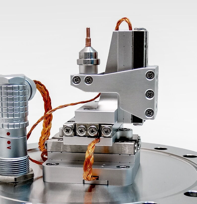 SmarAct UHV-compatible piezo positioner on a vacuum flange. The all-ceramic drive mechanism generates no outgassing and zero heat at hold, making piezo motors the natural choice for vacuum environments where convective cooling is unavailable. Source: SmarAct
Ultra-high vacuum (below 10^-8 mbar): Outgassing dominates. All materials must meet ASTM E595 (below 1% TML). Piezo motors with ceramic/metal construction are available from PI, SmarAct, and Attocube. Servo motors require extensive modification and cost 3 to 10 times the atmospheric version.
Cleanroom
Particle generation determines suitability. Ball screws and recirculating guides generate metallic particles. Piezo motor stages with flexure guides eliminate this source entirely. Lubricant outgassing from ball screw assemblies introduces chemical contamination; piezo motors have fewer organic materials. For ISO Class 5 (Class 100) and cleaner, piezo motor stages with flexure guides are the lowest-risk choice. See the EMI, magnetic, and cleanroom environments article for detailed contamination data.
Cryogenic Environments
PZT ceramics maintain piezoelectric function to liquid helium temperatures. The d33 coefficient drops roughly 50% at 77 K, reducing stroke but preserving functionality. PI PICMA ceramic technology is specified to -271 degrees C (2 K), suitable for superconducting magnet assemblies and particle physics detectors.
Servo and stepper motors face lubricant solidification (most greases solidify below -60 degrees C), magnetic property changes, and wiring embrittlement at cryogenic temperatures. Specialized cryogenic motors (Phytron, CDA InterCorp) exist but are expensive. Voice coils function at cryo if designed with appropriate materials, but SmCo magnets must replace NdFeB.
Non-Magnetic Environments
If the application is near magnetically sensitive equipment (electron microscopes, SQUID magnetometers, MRI systems, ion beam systems), the stray magnetic field from the actuator becomes a primary specification.
- Stepper and servo motors: Contain permanent magnets and current-carrying coils. Stray field at 100 mm: 0.1 to 10 mT depending on motor size and design.
- Voice coil actuators: Contain strong NdFeB magnets. Stray field at 100 mm: 0.5 to 5 mT. Magnetic shielding adds significant mass and volume.
- Piezo motors: No permanent magnets. No current-carrying coils during hold. Residual magnetic field: essentially zero. The Acuvi LTC300 piezo motor produces less than 1 nT stray field at 10 mm distance, which is below the noise floor of most magnetometers.
For MRI-compatible devices, electron-optical systems, and any application requiring fields below 0.5 mT at the actuator location, piezo motors are the only option that does not require magnetic shielding.
Radiation Environments
Piezo ceramics are radiation-hard to doses exceeding 10^9 rad (10^7 Gy). Electronic components (encoders, driver ICs) are the limiting factor, not the ceramic. Electromagnetic motors are similarly radiation-tolerant in the motor itself, but encoders and drive electronics define the system limit.
Question 5: What Is the Duty Cycle and Thermal Budget?
This final question addresses how the actuator will be used over time. Duty cycle, defined as the fraction of operating time spent in active motion versus holding, interacts powerfully with thermal budget to separate technologies.
High Duty Cycle (Above 80% Moving)
Applications that require near-continuous motion, such as scanning stages, conveyor positioning, and raster scanning in inspection systems, favor electromagnetic motors. Servo and stepper motors are designed for continuous rotation and sustain rated torque indefinitely within their thermal limits. Piezo motors face friction-tip wear under continuous operation; lifetime specifications of 10,000 to 100,000 hours are common, but these assume intermittent duty. At 100% duty, wear rates increase and lifetime may drop to 1,000 to 5,000 hours depending on speed, load, and environmental conditions.
Recommendation: Servo motor for continuous scanning above 10 mm/s. Stepper motor for continuous lower-speed applications where cost matters. Piezo motor only if environmental constraints (vacuum, cleanroom, non-magnetic) are mandatory.
Low Duty Cycle with Extended Hold (Below 20% Moving)
Applications that move infrequently but must hold position for extended periods, such as optics alignment, semiconductor fixture positioning, and calibration adjustments, strongly favor piezo motors and piezo stacks. These technologies hold position with zero electrical power through either friction preload (motors) or ceramic stiffness (stacks). There is no heat generation, no thermal drift, and no power supply required during hold.
Servo motors holding position dissipate continuous I^2*R power. A servo holding against a 20 N gravity load through a ball screw might consume 5 to 15 W, raising the local temperature by 5 to 20 degrees C over several hours. In metrology applications, this thermal perturbation directly degrades measurement accuracy.
Recommendation: Piezo motor or piezo stack. The energy savings compound over time, and the thermal stability advantage is often more valuable than the energy savings.
Thermally Sensitive Metrology
For applications where thermal stability is the primary performance metric, such as interferometric measurement, wafer metrology, coordinate measuring machines, and optical frequency standards, the thermal output of the actuator directly limits system performance.
Consider: a servo dissipating 10 W on an aluminum stage with 2 K/W thermal resistance raises stage temperature by 20 degrees C. At 23 ppm/K CTE, a 200 mm aluminum stage grows by 92 micrometers, dwarfing the motor's resolution specification. Piezo motors dissipating 0 W at hold introduce negligible thermal perturbation. This is why nearly every nanometer-class metrology system uses piezo actuation: not because the motors are more precise, but because they generate less heat.
High-Speed Continuous Scanning
For applications requiring continuous constant-velocity scanning (surface profiling, wafer inspection, laser processing), the actuator must maintain smooth, jitter-free motion for extended periods. Direct-drive linear servo motors excel here because they produce continuous force without mechanical transmission artifacts. Ironless linear motors (PI V-551, Aerotech ABL1500) provide zero-cogging scanning with velocity ripple below 0.01%.
Piezo motors are less suited for continuous scanning because the friction-drive mechanism inherently produces micro-vibrations at the ultrasonic drive frequency. For scanning applications, voice coil actuators offer another excellent option at short strokes, with constant force and zero cogging.
The Decision Tree in Practice
Working through the five questions produces rapid convergence.
Step 1 (Resolution): Above 10 um, keep all options. Between 1 and 10 um, eliminate steppers unless you add closed-loop control. Below 1 um, eliminate steppers entirely; proceed with servo (direct-drive), voice coil, and piezo. Below 100 nm, eliminate voice coil unless stroke is below 1 mm; eliminate servo unless you can afford air bearings and interferometric feedback.
Step 2 (Speed): Above 500 mm/s, servo motor, always. Between 50 and 500 mm/s, servo preferred; piezo viable only if resolution is below 1 um and stroke under 100 mm. Between 1 and 50 mm/s, move to force (this is the overlap zone). Below 1 mm/s, piezo strongly preferred.
Step 3 (Force): Above 100 N continuous, servo with screw drive (or PICA Power stacks for micro-stroke). Between 10 and 100 N, servo preferred; piezo competitive if environment demands it. Below 10 N, all survivors remain viable.
Step 4 (Environment): Vacuum below 10^-3 mbar, cleanroom ISO 5 or better, non-magnetic, or cryogenic below -40 degrees C: strong preference for piezo. Atmospheric and magnetically insensitive: no constraint.
Step 5 (Duty Cycle): High duty (above 80% moving) favors servo or stepper. Extended hold favors piezo. Thermal sensitivity amplifies the zero-power-hold advantage.
If two technologies survive, conduct a focused trade study on system cost, integration complexity, and vendor support rather than re-evaluating the full field.
Common Mistakes in Actuator Selection
The same mistakes appear repeatedly across industries.
Over-Specifying Resolution
An engineer specifies 10 nm resolution for a process requiring 1 micrometer accuracy because "better resolution can't hurt." It can. Higher resolution demands more expensive encoders, stiffer structures, better vibration isolation, and more sophisticated controllers. A 10 nm system may cost 5 to 10 times more than a 1 micrometer system and perform worse because stiffness requirements conflict with other constraints. The remedy: specify resolution from the process tolerance. If the workpiece tolerance is 2 micrometers, the actuator resolution should be 200 to 500 nm (4 to 10 times finer), not 10 nm.
Ignoring Duty Cycle
Selecting a servo motor for an axis that moves for 30 seconds then holds for 5 minutes overlooks the thermal cost: the servo dissipates full holding power during every 5-minute hold. Over an 8-hour shift, hundreds of watt-hours accumulate as heat. A piezo motor dissipates zero energy during hold.
Confusing Stroke with Resolution
Specifying 100 mm travel at 10 nm resolution demands a dynamic range of 10^7 from a single device. Very few actuators deliver this. A two-stage coarse/fine architecture (servo for stroke, piezo stack for fine positioning) is often cheaper, faster to implement, and more robust.
Using Voice Coils for Static Holding
Voice coils produce force proportional to current with zero detent or friction force. Holding position against gravity requires continuous current, generating I^2*R heat that degrades the coil and the surrounding system. Using a voice coil where a piezo motor or stepper would provide passive holding is a thermal budget error.
Neglecting the Operating Environment
Selecting a servo for vacuum "because we can get a vacuum-compatible version" ignores the thermal problem. Vacuum grease and feedthroughs address outgassing but do nothing about the 20 W of heat that can no longer escape by convection. The motor requires radiative cooling or conductive heat sinking, both of which add design effort and cost.
Selecting Steppers for Sub-Micron Work
Stepper motors with lead screws are sometimes chosen for sub-micron work based on calculated microstep size. A 1/256 microstep on a 0.5 mm pitch lead screw theoretically produces a 2 nm step. In practice, the lead screw has 5 to 20 um pitch errors, 1 to 10 um backlash, and the motor torque profile during microstepping is sinusoidal, not staircase-shaped. Below 1/16 microstepping, torque is too low to overcome static friction reliably. Actual MIM rarely goes below 1 um.
Multi-Technology Comparison Table
The following table compares six actuator architectures across the parameters most relevant to precision positioning applications. Ranges represent typical commercially available products, not theoretical limits. For a deeper analysis of the physics underlying these tradeoffs, see piezo motion technologies compared.
| Parameter | Piezo Stack (Flexure) | Amplified Piezo | Ultrasonic Piezo Motor | Voice Coil | Servo + Ball Screw | Direct-Drive Linear Motor |
|---|---|---|---|---|---|---|
| Stroke | 5 to 500 um | 50 um to 2 mm | 5 to 300+ mm | 0.1 to 50 mm | 25 to 2,000+ mm | 50 to 2,000+ mm |
| Resolution | 0.05 to 1 nm | 1 to 10 nm | 0.5 to 50 nm | 5 to 500 nm | 50 nm to 5 um | 5 to 100 nm |
| Continuous Force | 10 to 30,000 N | 50 to 3,300 N | 0.3 to 600 N | 0.5 to 200 N | 50 to 10,000 N | 10 to 5,000 N |
| Max Velocity | N/A (static) | N/A (static) | 10 to 1,000 mm/s | 10 to 500 mm/s | 10 to 1,000 mm/s | 100 to 6,000 mm/s |
| Bandwidth (-3 dB) | 1 to 50 kHz | 100 Hz to 5 kHz | 10 to 500 Hz | 50 to 2,000 Hz | 10 to 200 Hz | 50 to 500 Hz |
| Power at Hold | 0 W | 0 W | 0 W | I^2*R (high) | I^2*R (moderate) | I^2*R (moderate) |
| Heat Generation | Negligible | Negligible | Low (during motion) | High | Moderate to High | Moderate |
| Magnetic Field | None | None | None | Strong (NdFeB) | Moderate | Moderate to Strong |
| Vacuum Suitability | Excellent | Excellent | Excellent | Good (derate) | Fair (thermal) | Fair (thermal) |
| Relative Cost (single axis) | $1,000 to $15,000 | $500 to $5,000 | $2,000 to $12,000 | $500 to $5,000 | $1,000 to $10,000 | $5,000 to $50,000 |
| Typical Size | Compact | Compact | Compact | Medium | Large | Large |
Worked Selection Examples
The following five examples walk through the five-question framework for real-world applications, demonstrating how the sequential filtering process converges on a technology choice.
Example 1: Semiconductor Wafer Z-Focus
Application: Z-axis autofocus for a 300 mm wafer inspection tool. The optics assembly (mass: 200 g) must track wafer surface topography during continuous X-Y scanning.
- Resolution needed: 50 nm (process tolerance: 500 nm depth of focus)
- Speed needed: 5 mm/s for focus tracking; 20 mm/s for wafer load/unload repositioning
- Stroke needed: 2 mm (to accommodate wafer bow and cassette variation)
- Force needed: 2 N (gravity on 200 g optics)
- Environment: ISO Class 3 cleanroom, vibration-isolated granite
Q1 (Resolution): 50 nm eliminates steppers. Servo (direct-drive), voice coil, and piezo remain.
Q2 (Speed/Stroke): 20 mm/s and 2 mm stroke are within range for all three survivors.
Q3 (Force): 2 N is trivial for all three.
Q4 (Environment): ISO Class 3 cleanroom strongly favors piezo motor or voice coil (no ball screw particles). Direct-drive servo with air bearing is possible but oversized.
Q5 (Duty Cycle): During inspection, the Z-axis tracks continuously (high duty). During wafer exchange, it holds position. The thermal budget is critical; any heat near the optics degrades image quality.
 Semiconductor wafer positioning stage. Cleanroom compatibility, thermal stability, and sub-100 nm resolution requirements make piezo motors the dominant technology for wafer inspection Z-focus axes. Source: PI
Decision: Piezo motor (PI PILine U-521 or similar) for zero-power hold, cleanroom compatibility, and minimal thermal output. A piezo flexure stage (PI P-721 PIFOC with 100 um travel) would also work if the 2 mm stroke requirement can be reduced to 100 um by mechanical pre-positioning. For the full 2 mm stroke, a voice coil with counterbalance spring is the alternative, accepting higher thermal output during tracking.
Example 2: CNC Machine Tool Axis
Application: X-axis of a vertical milling center. 500 mm travel, cutting forces up to 2,000 N, rapid traverse at 30 m/min (500 mm/s).
- Resolution needed: 5 um (part tolerance: 50 um)
- Speed needed: 500 mm/s rapid; 50 mm/s cutting feed
- Stroke needed: 500 mm
- Force needed: 2,000 N continuous cutting force; 4,000 N peak during interrupted cuts
- Environment: Industrial, coolant mist, chips, temperature variation of 10 degrees C
Q1 (Resolution): 5 um is achievable by all technologies. No elimination.
Q2 (Speed/Stroke): 500 mm/s at 500 mm stroke eliminates all piezo motors, all voice coils, and all piezo stacks immediately. Only servo motors and stepper motors remain. Stepper motors lose torque at 500 mm/s and are marginal.
Q3 (Force): 2,000 N continuous eliminates stepper motors (typical NEMA 34 stepper with lead screw: 500 to 1,000 N maximum). Only servo motors remain.
Q4 (Environment): Industrial environment imposes no special constraint. Standard servo motor with IP65 protection.
Q5 (Duty Cycle): High duty cycle, continuous operation for hours. Servo motors are designed for exactly this.
Decision: Servo motor with precision ball screw (C3 or C5 grade) and linear encoder for compensation. Specific options include the Fanuc Alpha iF servo series or Siemens 1FK7 with a THK or NSK ball screw. This is the straightforward case where the five questions converge rapidly.
Example 3: MRI-Compatible Surgical Robot Joint
Application: Rotary joint for a needle-insertion robot operating inside a 3T MRI bore. The robot must position a biopsy needle while the MRI provides real-time imaging guidance.
- Resolution needed: 0.1 mm (100 um) angular equivalent at the needle tip (50 mm lever arm, so roughly 2 mrad or 0.1 degree)
- Speed needed: 5 mm/s at the needle tip (slow, deliberate insertion)
- Stroke needed: 200 mm insertion depth; 90 degrees rotation
- Force needed: 10 N insertion force; 0.5 Nm rotation torque
- Environment: 3T MRI magnetic field (extremely sensitive to ferromagnetic materials and electromagnetic emissions)
Q1 (Resolution): 100 um is achievable by all technologies. No elimination.
Q2 (Speed/Stroke): 5 mm/s and 200 mm stroke are within range for piezo motors, servos, and steppers. No elimination.
Q3 (Force): 10 N and 0.5 Nm are modest. All technologies qualify.
Q4 (Environment): 3T MRI field. This is the decisive question. Stepper motors: permanent magnets and steel laminations are ferromagnetic. Eliminated. Servo motors: permanent magnets are ferromagnetic. Eliminated. Voice coils: NdFeB magnets are ferromagnetic. Eliminated. Only piezo motors survive. They contain no permanent magnets, no ferromagnetic materials (with appropriate construction), and produce no stray magnetic field.
Q5 (Duty Cycle): Low duty; the needle advances slowly and then holds. Zero-power hold from piezo friction preload is ideal during imaging sequences, as it generates no electromagnetic interference.
Decision: Ultrasonic piezoelectric motor. Specifically, motors from Shinsei (USR60 traveling-wave type), PiezoMotor (Piezo LEGS), or custom designs from Nanomotion. The Acuvi LTC300 with its sub-1 nT stray field at 10 mm is particularly suited if linear actuation is needed. Multiple vendors now produce MRI-conditional robot systems using piezo motors exclusively.
Example 4: Laser Beam Steering Mirror
Application: Fast tip-tilt mirror for laser beam pointing in an adaptive optics system. The mirror (mass: 5 g) must correct atmospheric turbulence at up to 1 kHz bandwidth.
- Resolution needed: 0.1 urad (approximately 0.5 nm at a 5 mm lever arm)
- Speed needed: Small angular excursions at high bandwidth (1 kHz), not high linear velocity
- Stroke needed: Plus/minus 2 mrad mechanical (plus/minus 4 mrad optical), equivalent to approximately plus/minus 10 um at the actuator
- Force needed: Less than 0.5 N (5 g mirror mass, low friction)
- Environment: Laboratory, vibration-isolated optical table, temperature-controlled room
Q1 (Resolution): 0.5 nm equivalent at the actuator eliminates steppers, servos, and most voice coils. Only piezo stacks and high-end voice coils remain.
Q2 (Speed/Stroke): The requirement is bandwidth, not linear speed. Plus/minus 10 um stroke at 1 kHz. Piezo stacks are naturally suited: a 10 mm stack has a resonance frequency of 50 to 100 kHz, providing ample bandwidth margin. Voice coils can achieve 1 kHz bandwidth for small strokes.
Q3 (Force): Below 0.5 N. Both technologies handle this trivially.
Q4 (Environment): No special constraint. Laboratory conditions.
Q5 (Duty Cycle): Continuous operation for hours during observations. Piezo stacks dissipate power proportional to capacitance, frequency, and voltage amplitude. At 1 kHz with 10 um stroke, a typical stack dissipates 0.5 to 2 W, which is manageable. Voice coils dissipate I^2*R continuously.
Decision: Piezo stack actuators in a tip-tilt flexure mount. Products include the PI S-330 tip-tilt platform (2 mrad, 1 kHz, capacitive sensor option) or Physik Instrumente S-340 for larger angles. Voice coil tip-tilt mirrors (such as the Optics In Motion OIM201) are the alternative, offering slightly larger stroke at the expense of power consumption and thermal output. For the stated 1 kHz bandwidth with sub-microradian resolution, the piezo stack approach is more proven and widely deployed.
Example 5: Fiber Alignment 6-DOF
Application: Automated alignment of a single-mode fiber to a photonic integrated circuit (PIC) facet. The system must find and maintain the coupling peak with better than 50 nm resolution in X, Y, and Z, and 0.01 degree in tip and tilt.
- Resolution needed: 50 nm linear, 0.01 degree angular
- Speed needed: 10 mm/s search scan; sub-mm/s fine alignment
- Stroke needed: 10 mm search range per axis
- Force needed: Less than 1 N (fiber and holder mass: 10 to 50 g)
- Environment: Cleanroom ISO 6, temperature-controlled to plus/minus 0.5 degrees C
- Volume: 200 systems per year
Q1 (Resolution): 50 nm eliminates steppers. Servo, voice coil, and piezo remain.
Q2 (Speed/Stroke): 10 mm/s and 10 mm stroke are within range for all three.
Q3 (Force): Below 1 N. All technologies work.
Q4 (Environment): Cleanroom ISO 6 favors piezo (no ball screw particles). Voice coil is acceptable. Direct-drive servo with air bearing is oversized and expensive.
Q5 (Duty Cycle): During alignment scanning, the axes move continuously (moderate duty). After alignment, the fiber is bonded and the system holds position during curing (minutes). Zero-power hold during curing prevents thermal drift that could shift the optimized coupling position.
Decision: Piezo stick-slip motors in a 6-DOF hexapod or XYZ-tip-tilt configuration. The SmarAct SMARPOD 70.42 provides 6 degrees of freedom with 1 nm resolution from a compact package. PI also offers hexapod solutions using piezo motors (H-811.S2, using PILine or NEXACT drives). For a lower-cost approach, individual SmarAct SLC-2430 stages can be stacked for X, Y, Z with separate tip-tilt stages. The zero-power hold and cleanroom compatibility make piezo stick-slip the standard technology for this application, and SmarAct has become the dominant vendor in photonic packaging alignment.
Environmental Decision Matrix
The following table maps operating environments directly to technology suitability, consolidating the environmental analysis from Question 4. Green indicates standard suitability. Yellow indicates possible with modifications. Red indicates generally unsuitable.
| Environment | Piezo Stack | Piezo Motor | Voice Coil | Servo + Ball Screw | Direct-Drive Linear | Stepper + Lead Screw |
|---|---|---|---|---|---|---|
| Atmospheric (lab/industrial) | Suitable | Suitable | Suitable | Suitable | Suitable | Suitable |
| Rough Vacuum (to 10^-3 mbar) | Suitable | Suitable | Suitable (derate) | Modified (grease) | Modified (grease) | Modified (grease) |
| High Vacuum (10^-3 to 10^-8 mbar) | Suitable | Suitable | Marginal (thermal) | Difficult (thermal) | Difficult (thermal) | Difficult (thermal) |
| Ultra-High Vacuum (below 10^-8 mbar) | Suitable (UHV materials) | Suitable (UHV materials) | Marginal | Expensive modifications | Expensive modifications | Rarely used |
| Cleanroom ISO 5 or better | Suitable | Suitable | Suitable | Marginal (particles) | Suitable (no screw) | Marginal (particles) |
| Cryogenic (below -40 degrees C) | Suitable (reduced stroke) | Suitable (reduced stroke) | Modified (material) | Specialized motors | Specialized motors | Specialized motors |
| Non-Magnetic (below 0.5 mT) | Suitable | Suitable | Not suitable | Not suitable | Not suitable | Not suitable |
| Radiation (above 10^6 rad) | Suitable (ceramic is rad-hard) | Suitable (ceramic is rad-hard) | Suitable | Suitable | Suitable | Suitable |
| High Humidity (above 80% RH) | Marginal (electrode protection) | Suitable (sealed) | Suitable (sealed) | Suitable (sealed) | Suitable (sealed) | Suitable (sealed) |
The pattern is clear: piezo technologies have the broadest environmental compatibility. For applications combining multiple constraints (cryogenic vacuum near a superconducting magnet, for instance), piezo actuators are frequently the only viable option without extensive custom engineering.
When No Single Technology Works
Some applications specify requirements that no single actuator can satisfy. The most common case: long stroke combined with nanometer resolution. A 200 mm travel range at 10 nm resolution demands a dynamic range of 2 times 10^7. Few single-stage systems deliver this, and those that do (air-bearing stages with interferometric feedback) cost $50,000 to $150,000 per axis.
Multi-Stage (Coarse/Fine) Architecture
The solution is to decompose the motion into two stages. A coarse stage provides the long stroke with moderate resolution. A fine stage, riding on the coarse stage, provides nanometer resolution over a short stroke. The two stages operate in a coordinated control loop.
Ball screw + piezo flexure fine stage: The most common combination. A servo motor with ball screw provides 200 mm of travel at 1 micrometer resolution. A piezo stack with capacitive sensor on the moving platform provides plus/minus 50 micrometers of fine travel at 0.5 nm resolution. The coarse stage positions to within 10 micrometers; the fine stage corrects the remaining error. System resolution: 0.5 nm. System travel: 200 mm. Data from the U.S. Department of Energy (OSTI) confirms that dual-stage architectures routinely achieve 10 nm accuracy over 200 mm travel in synchrotron beamline monochromators and nanolithography systems.
Servo + piezo motor: For applications needing longer fine-stage travel (5 to 50 mm) than a piezo stack can provide, a piezo motor serves as the fine stage with 1 nm resolution over 20 mm, accommodating the coarse stage's repeatability error.
Stepper + voice coil: For cost-sensitive applications, a stepper provides long coarse travel and a voice coil provides fine positioning with constant force. Common in autofocus systems and disk drive head positioning.
The load-stroke-resolution tradeoffs article details why this decomposition is necessary and how performance boundaries define the optimal coarse/fine split point.
Design Guidelines for Multi-Stage Systems
Practical rules for multi-stage design:
- Fine stage stroke must exceed coarse stage repeatability by 2 to 5 times. If the coarse stage has 5 um repeatability, the fine stage needs 10 to 25 um of stroke.
- Fine stage bandwidth must exceed coarse stage bandwidth by 5 to 10 times for the coordinated loop to function.
- Minimize fine stage mass. Piezo stacks in flexures (50 to 200 g) are lighter than piezo motor stages (200 to 500 g) but have shorter stroke.
- Cable routing must accommodate coarse stage travel without introducing forces that degrade fine stage performance.
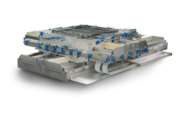
 Multi-stage stacked architecture: an XY linear stage (bottom) carries a rotation stage and Z-axis stage (top), combining long coarse travel with fine positioning at the payload. This approach extends single-technology performance limits by distributing requirements across specialized stages. Source: PI
Practical Summary
The five-question framework reduces actuator selection from an open-ended evaluation to a structured elimination process. Here are the condensed decision rules:
If you need resolution below 100 nm: use piezo (motor for travel above 1 mm; stack/flexure for travel below 500 um).
If you need speed above 500 mm/s: use a servo motor.
If you need force above 100 N with long stroke: use a servo motor with ball screw or roller screw.
If you operate in vacuum, cleanroom, cryogenic, or non-magnetic environments: use piezo unless a specific parameter (speed, force, stroke) makes it impossible.
If you hold position for extended periods: use piezo (zero power, zero heat, zero drift).
If you need long stroke with nanometer resolution: use a multi-stage coarse/fine architecture.
If no environmental or extreme resolution constraint exists and the speed requirement is above 50 mm/s: default to a servo motor. It has the deepest supply chain, the most mature control ecosystem, and the broadest vendor selection.
For head-to-head comparisons between specific technology pairs, the dedicated articles provide detailed analysis: piezo versus servo for the most common selection debate, piezo versus stepper for cost-sensitive applications, and piezo versus voice coil for short-stroke constant-force applications. The piezo motion technologies compared article covers the internal selection among piezo variants (stack, amplified, ultrasonic, stick-slip, NEXLINE walking drive).
This framework does not guarantee the optimal choice in every case. But it eliminates obviously wrong choices in the first ten minutes and focuses your engineering effort on the one or two candidates most likely to succeed. That alone saves weeks of wasted effort and prevents the costly mistake of committing to a technology that fails on a fundamental requirement discovered too late to change course.