技术对比
Understanding load-stroke-resolution tradeoffs across actuator technologies
The fundamental physics that prevent any single actuator from excelling at force, travel, and precision simultaneously
Understanding Load-Stroke-Resolution Tradeoffs Across Actuator Technologies
Every actuator technology occupies a bounded region in load-stroke-resolution space. No technology excels at all three parameters simultaneously, and the constraints are rooted in fundamental physics, not engineering shortcuts. A piezoelectric stack delivers extraordinary stiffness and sub-nanometer resolution but is limited to micrometers of travel. A servo motor covers hundreds of millimeters at kilonewton forces but cannot resolve below a micrometer without extraordinary effort. A voice coil provides nanometer-level positioning over millimeters of stroke but runs into thermal walls when you demand more force.
These boundaries are not the result of poor design. They are consequences of material properties, thermodynamics, and signal-to-noise ratios. Understanding them is the difference between specifying a system that performs well and specifying one that cannot exist. When an engineer writes "200 mm travel, 10 nm resolution, 500 N continuous force" on a requirements document, they have almost certainly described an impossible single-stage system. Recognizing that fact early, and knowing how to decompose the requirement into achievable subsystems, is the core skill this article aims to build.
This article maps the performance boundaries for six actuator families: piezoelectric stacks, amplified piezoelectric actuators, piezoelectric motors, voice coil actuators, servo and linear motors, and stepper motors. It also covers the flexure mechanisms that guide many of these actuators, the multi-stage architectures that extend beyond single-technology limits, and the practical rules of thumb for selecting among them.
The Three-Way Tradeoff
The load-stroke-resolution constraint is sometimes described as "pick two of three," and while this oversimplifies the physics, the intuition is correct:
High force + long stroke = poor resolution. Moving large loads over long distances means high energy transfer, which means heat, vibration, and large mechanical structures with proportionally large error sources. Ball screws introduce backlash and pitch error. Linear motors generate substantial electromagnetic noise. Thermal expansion of long guideways creates drift.
High resolution + long stroke = low force. Maintaining nanometer precision over centimeters of travel demands air bearings, interferometric encoders, granite bases, and vibration isolation. The resulting systems are large, expensive, and structurally compliant. Their force capacity is limited by thermal sensitivity and bearing stiffness.
High force + high resolution = short stroke. Piezoelectric stacks achieve kilonewton forces with picometer resolution, but only over micrometers of travel. The strain limit of the ceramic sets an absolute ceiling on displacement relative to actuator length.
This three-way constraint is not an engineering limitation waiting to be overcome by clever design. It is a consequence of thermodynamics (heat generation scales with force times velocity), material science (strain limits, thermal expansion coefficients), and information theory (signal-to-noise ratios in sensors and drivers). Every new actuator technology discovered in the last fifty years has landed inside the same bounded envelope, simply occupying a different region of it.
Each pairing of parameters has a distinct physical mechanism that creates the boundary. Understanding these mechanisms, rather than memorizing technology specifications, is what allows engineers to evaluate new actuator technologies quickly and to recognize when a vendor's specification sheet is claiming performance outside physically plausible bounds.
Piezoelectric Stack Actuators
The simplest piezoelectric actuator is a stack of PZT ceramic layers, each expanding when voltage is applied. The physics are governed by a single equation:
delta_L = d33 x V x N
where d33 is the piezoelectric charge coefficient, V is the applied voltage, and N is the number of layers. For PZT-5A, d33 is approximately 390 pm/V. For PZT-5H, d33 is approximately 593 pm/V. Newer PMN-PT single crystals reach d33 values of 2000 pm/V, though at substantially higher cost and with temperature sensitivity that limits their practical use.
The total free displacement of a stack actuator is constrained to approximately 0.1% to 0.15% of the actuator's physical length. This is a material strain limit, not a design parameter. A 10 mm stack produces 10 to 15 micrometers. A 100 mm stack produces 100 to 150 micrometers. To get 1 mm of stroke from a bare stack, you would need a stack roughly 700 mm long, which would be fragile, expensive, and resonant at impractically low frequencies.
Blocking Force and Load Lines
The blocking force of a piezo stack is the maximum force it can exert when its displacement is completely constrained. It equals the product of the stack stiffness and the free displacement:
F_block = k_stack x delta_L_free
The PI PICMA P-885.55, a widely used compact multilayer actuator, has a free displacement of 14 micrometers, a blocking force of 850 N, and a stiffness of approximately 50 N/micrometer. Its resonant frequency is near 60 kHz, making it suitable for dynamic applications at kilohertz bandwidths.
The larger P-888.55 raises the blocking force to 3,400 N while maintaining the same stroke, because its larger cross-section provides higher stiffness. The PICA Power series spans a broad range: 5 to 180 micrometers of stroke with blocking forces from 1,200 N to 70,000 N.
For preloaded designs, the P-242 and P-246 series deliver up to 120 micrometers of stroke with 30,000 N of push force and 3,500 N of pull force. The preload spring that enables pull force must be carefully selected: its stiffness should not exceed approximately 10% of the piezo stack stiffness, or the preload will consume a significant fraction of the available displacement.
The practical output displacement under load follows a linear load line. As external stiffness increases, the output displacement decreases linearly. When the external stiffness equals the piezo stiffness, the output displacement is halved, and the output force is half the blocking force. This load line behavior means that the system designer must account for the stiffness of everything the piezo pushes against: the workpiece, the mounting structure, and any preload mechanisms.
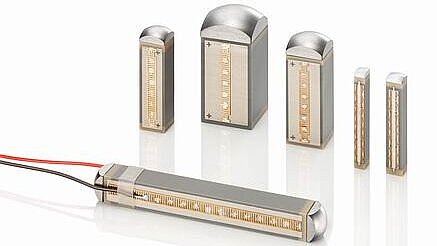 PI PICMA multilayer stack actuators. The co-fired ceramic construction provides sub-nanometer resolution, kilonewton blocking force, and bandwidth measured in tens of kilohertz. Stroke scales linearly with stack length at approximately 0.1% of actuator height. Source: PI
Where piezo stacks dominate: Strokes below 200 micrometers, resolution below 1 nm, stiffness above 10 N/micrometer, bandwidth above 1 kHz. No other actuator technology competes in this region.
Amplified Piezo Actuators
Mechanical amplification, typically through flexure lever mechanisms, trades force for stroke. This is not free; the tradeoff follows strict scaling laws. If the amplification ratio is A, then:
- Stroke increases by factor A
- Blocking force decreases by factor A
- Stiffness decreases by factor A squared
- Resonant frequency decreases by factor approximately sqrt(A)
The force-stroke product is roughly conserved for a given actuator shell size. This means you can redistribute the energy between force and displacement but cannot create more of either without a larger actuator.
The Cedrat APA Range
Cedrat Technologies manufactures one of the most complete ranges of amplified piezo actuators, and their product line illustrates the amplification tradeoff clearly:
| Model | Free Stroke (um) | Blocking Force (N) | Stiffness (N/um) | Resonant Freq (Hz) | Force x Stroke (N-um) |
|---|---|---|---|---|---|
| APA30uXS | 34 | 3.7 | 0.11 | 4,800 | 126 |
| APA60ML | 65 | 3,300 | 51 | 2,600 | 214,500 |
| APA300ML | 300 | 540 | 1.8 | 760 | 162,000 |
| APA2000L | 2,000 | 62 | 0.031 | 87 | 124,000 |
Several patterns emerge from this table. The APA30uXS and APA2000L have comparable force-stroke products (roughly 125,000 N-um) despite dramatically different distributions of force and stroke. The APA2000L achieves 2 mm of travel, approaching the territory of voice coil actuators and piezo motors, but with only 62 N of blocking force and a stiffness of 0.031 N/micrometer. Compare that to a bare stack like the P-885.55, which has stiffness of 50 N/micrometer: the APA2000L has roughly 1,600 times less stiffness.
The resonant frequency tells the same story. The APA30uXS resonates at 4,800 Hz, providing kilohertz-class bandwidth. The APA2000L resonates at 87 Hz, limiting its useful bandwidth to perhaps 20 to 30 Hz. For high-speed scanning or vibration control, the long-stroke amplified designs are simply too slow.
The mid-range APA60ML is notable because it maintains substantial force (3,300 N blocking) and stiffness (51 N/micrometer) with 65 micrometers of stroke and a resonant frequency of 2,600 Hz. This represents a modest amplification of a large stack, preserving much of the stack's native stiffness and bandwidth.
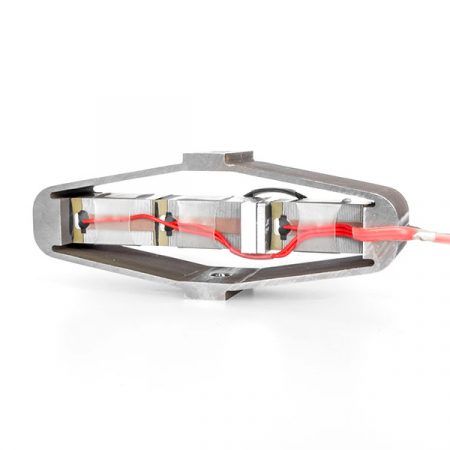 Cedrat APA300ML amplified piezo actuator. The diamond-shaped flexure shell converts the internal stack's 15 micrometer displacement into 300 micrometers of output stroke, illustrating the force-for-stroke tradeoff: 540 N blocking force (versus 3,400 N for the bare stack) at 20x the travel. Source: Cedrat Technologies
Where amplified piezos dominate: Strokes of 50 to 500 micrometers when moderate force (100 to 1,000 N) and moderate bandwidth (100 to 1,000 Hz) are acceptable. Active vibration control of optical mounts, adaptive optics, and fast tool servos for diamond turning are typical applications.
Piezoelectric Motors: Ultrasonic, Stick-Slip, and Walking
Piezoelectric motors break free of the stack stroke limit entirely by converting oscillatory piezo motion into continuous linear or rotary travel. Instead of expanding a stack by micrometers, these motors use piezoelectric vibration at ultrasonic frequencies to push a runner through friction contact, achieving unlimited stroke in principle.
Three main architectures exist. Ultrasonic motors use a traveling or standing wave to drive a friction contact at 20 to 200 kHz. Stick-slip motors exploit the difference between static and dynamic friction to advance a runner in nanometer-scale steps. Walking motors (such as the PI NEXLINE series) use multiple piezo legs that grip, push, and release in coordinated sequences, analogous to biological locomotion.
Resolution
The resolution of piezo motors is determined by the contact dynamics and the control architecture. Each "step" has a minimum increment set by the contact stiffness, preload, and surface conditions. Typical minimum incremental motion ranges from 1 nm (for the best walking designs) to 100 nm (for simpler stick-slip devices). This is vastly better than stepper or servo motor systems but coarser than bare piezo stacks.
Force
Force ranges widely across motor types. The Nanomotion Edge motor produces approximately 0.35 N of continuous force, suitable for lightweight optics positioning. At the other extreme, the PI N-216 NEXLINE walking motor generates up to 600 N. Between these extremes, most ultrasonic linear motors deliver 1 to 50 N.
Speed
Speed also spans a wide range. The PI NEXACT series, optimized for precision and force, reaches approximately 10 mm/s. The Xeryon XLS series, optimized for speed, achieves up to 1,000 mm/s. Most general-purpose piezo motor stages operate at 100 to 400 mm/s.
The Shifted Tradeoff
With unlimited stroke available, the tradeoff for piezo motors shifts from force-stroke-resolution to force-speed-wear rate. Higher force requires higher preload on the friction contact, which increases wear. Higher speed increases the number of friction cycles per second, also increasing wear. The contact surfaces (typically alumina ceramic) have finite lifetimes measured in thousands of kilometers of cumulative travel. For applications with moderate duty cycles (positioning rather than continuous scanning), wear is rarely a practical concern. For high-duty scanning applications, contact lifetime becomes a system-level design parameter.
Where piezo motors dominate: Millimeter to centimeter strokes at sub-micrometer resolution with zero-power holding, compact form factor, and no magnetic emissions. See the detailed comparison in piezo vs. servo and piezo vs. voice coil.
Voice Coil Actuators
Voice coil actuators operate on the Lorentz force principle:
F = k x B x L x I x N
where B is the magnetic flux density, L is the conductor length in the field, I is the current, N is the number of turns, and k is a geometry-dependent constant. The motor constant Km, which expresses the force produced per square root of power dissipated, is a key figure of merit. Critically, Km is inversely proportional to stroke length: longer magnetic gaps require weaker average field or more magnet mass.
Representative Products
The H2W Technologies NCC08-75-3000-3X is a high-performance voice coil with 20 mm of stroke, 1,330 N of continuous force, and 4,000 N of peak force. The 3:1 ratio between peak and continuous force is typical and reflects the thermal limit: peak force can be sustained only for short durations before the coil overheats. The motor constant is 323 N per square root of watt, indicating high efficiency for its class.
BEI Kimco manufactures voice coils with strokes up to 100 mm and continuous forces up to 1,000 N. Beyond approximately 150 mm of stroke, voice coil design becomes impractical because the magnetic gap length, magnet mass, and coil mass all grow to the point where force density collapses.
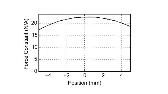
Force Constancy
A significant advantage of voice coils is force constancy over the stroke. Because the coil moves through a uniform magnetic field, the force-to-current ratio is constant to within approximately 5% over the full travel range. This makes voice coils ideal for applications requiring constant force application, such as active vibration isolation and precision load testing.
Resolution
Voice coil resolution is limited by current noise and the position sensor. With a low-noise current amplifier and a capacitive or interferometric position sensor, voice coils routinely achieve 100 nm resolution and can reach below 10 nm in carefully designed systems. However, achieving this requires an external position sensor (voice coils have no inherent position feedback) and a high-bandwidth servo loop.
Thermal Limits
The primary force ceiling for voice coils is thermal. Force is proportional to current, and heat dissipation is proportional to current squared. Doubling the continuous force requires four times the cooling capacity. This I-squared-R relationship creates a steep practical boundary: voice coils with high force ratings are physically large, require active cooling, and are expensive.
Moving Coil vs. Moving Magnet
Voice coil actuators come in two topologies. Moving coil designs fix the magnet assembly and move the coil, which minimizes moving mass but requires flexible cable management for the coil leads. Moving magnet designs fix the coil and move the magnet assembly, which simplifies cable routing but increases moving mass (magnets are heavy). For high-bandwidth applications like active vibration isolation, the lower moving mass of moving coil designs is preferred. For applications where cable routing is critical or the coil generates unacceptable heat near the payload, moving magnet is the better choice.
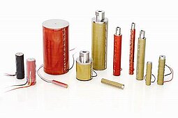
 Voice coil actuators and stages from PI. Force is proportional to current with zero cogging, making voice coils ideal for constant-force applications. The thermal penalty of continuous current (I squared R heating) limits their force ceiling and duty cycle. Source: PI
Where voice coils dominate: Short-stroke (1 to 50 mm) applications requiring force constancy, fast settling, and moderate resolution. Autofocus mechanisms, hard disk head positioning, active vibration cancellation, and precision force application.
Servo Motors and Linear Motors
Rotary Servo with Ball Screw
The combination of a rotary servo motor with a precision ball screw is the workhorse of industrial motion control. The screw provides mechanical advantage: a motor producing 1 Nm of torque through a 5 mm pitch screw generates approximately 1,100 N of linear force. This force multiplication comes with corresponding penalties in resolution.
Ball screw error sources include backlash (typically 1 to 20 micrometers, reducible to near zero with preloaded nuts), cumulative pitch error (3 to 10 micrometers per 300 mm for precision-grade screws), and elastic compliance under load. These errors set a practical resolution floor of 0.5 to 5 micrometers when using rotary encoders.
Adding a linear encoder on the moving platform bypasses screw errors but does not eliminate backlash (unless the controller compensates actively using the linear encoder signal). The Newport ILS250CC combines a 250 mm stroke with 0.1 micrometer resolution using a linear encoder. The PI M-230 series achieves 0.05 micrometer minimum incremental motion over 70 N of force with crossed-roller bearings and a linear encoder with interpolation electronics.
Direct-Drive Linear Motors
Direct-drive linear motors eliminate the ball screw entirely, removing backlash, pitch error, and coupling compliance from the error budget. The motor's forcer moves directly along a magnet track, and position is measured by a linear encoder attached to the same structure.
The Aerotech PRO165LM exemplifies the high end of this technology: 1,500 mm of travel, 5 nm minimum incremental motion, 2 m/s peak velocity, with air bearings and a precision granite base. The Aerotech BLMX series provides peak forces up to 4,252 N for heavy-load applications.
Two motor topologies dominate. Iron-core designs use a laminated iron stator that channels magnetic flux for high force density but introduces cogging (force ripple) and attraction forces between the forcer and magnet track. Ironless (or air-core) designs eliminate cogging and attraction forces at the cost of lower force density and higher cost per newton. The BLMX (iron-core) peaks at 4,252 N; the BLMH (ironless) peaks at 2,195 N. For applications demanding smooth velocity and nanometer positioning, ironless motors are strongly preferred despite their lower force.
The thermal limit is the primary force ceiling for linear motors. A forcer producing 500 N continuous might dissipate 300 to 800 W of heat, requiring liquid cooling jackets. For this reason, continuous force ratings are specified at a particular cooling condition (natural convection, forced air, liquid cooling).
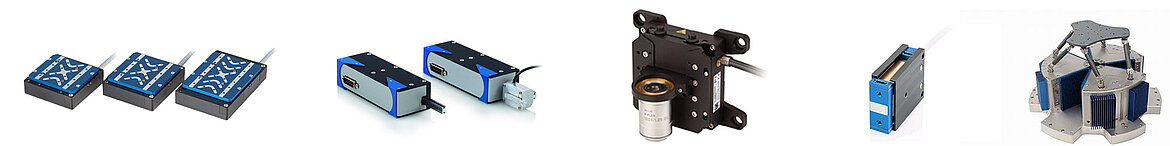
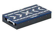 PI V-508 ironless linear motor stage. Direct-drive eliminates ball screw errors, enabling sub-micrometer resolution over hundreds of millimeters of travel. Ironless design provides zero cogging for smooth scanning. Source: PI
Where direct-drive linear motors dominate: Long stroke (100 mm to 3,000 mm), high speed (above 100 mm/s), and high resolution (below 1 micrometer) simultaneously. Semiconductor lithography stages, flat panel inspection, precision laser machining, and coordinate measuring machines.
Stepper Motors
Stepper motors are fundamentally different from the other technologies discussed here because their motion is inherently quantized. A typical 1.8-degree stepper has 200 full steps per revolution. Through a 2 mm pitch lead screw, each full step produces 10 micrometers of linear motion. Microstepping subdivides each full step electrically, with commercial drivers offering 256 microsteps per step (12.8 micrometers per microstep through a 2 mm pitch screw).
The Microstepping Resolution Myth
In practice, microstepping accuracy degrades rapidly at fine subdivision levels. Motor magnetic non-idealities, winding resistance variations, and detent torque create position errors that grow larger as microstep size decreases. At 1/256 microstepping, the actual step size might vary by 50% to 200% from the theoretical value. This is discussed in detail in the piezo vs. stepper comparison. Practical minimum incremental motion for a stepper motor system is 1 to 5 micrometers with a fine-pitch lead screw and closed-loop feedback, or 5 to 20 micrometers in open-loop mode.
Torque-Speed Characteristics
Stepper motors exhibit steep torque rolloff with increasing speed. A NEMA 17 stepper producing 0.4 Nm at low speed might deliver only 0.1 Nm at 1,000 RPM. A NEMA 23 stepper with 1.8 Nm rated holding torque might produce only 0.4 Nm at 1,000 RPM. This torque-speed characteristic is a fundamental consequence of the motor's inductance and the driver's voltage supply. Higher supply voltage pushes the torque rolloff to higher speeds but does not eliminate it.
For linear motion through a lead screw, this means the available force drops steeply at higher translation speeds. A NEMA 23 stepper with a 5 mm pitch screw provides approximately 2,000 N at low speed but perhaps 500 N at 100 mm/s.
Closed-Loop Steppers
Adding a linear encoder to a stepper system and closing a feedback loop can improve positioning accuracy substantially, but it does not overcome the fundamental resolution limit. The encoder can detect and correct for lost steps, thermal drift, and backlash, but the motor's minimum controllable force increment (set by the microstep current granularity and the detent torque) still limits minimum incremental motion to approximately 1 micrometer. Closed-loop stepper systems are increasingly popular in laboratory automation because they combine the low cost of stepper motors with the reliability of position feedback, but they should not be confused with servo-class performance.
Where steppers dominate: Applications requiring above 5 micrometer resolution at the lowest possible cost. Laboratory automation, 3D printing, CNC routing, sample handling, and any application where cost per axis below $500 matters more than extreme precision.
 Piezo actuator force-displacement (load line) diagram. The operating point moves along the diagonal: maximum displacement at zero force (free stroke) and maximum force at zero displacement (blocking force). External load stiffness determines where the system operates on this line. Source: PI
Flexure Mechanisms: The Guidance Tradeoff
Many precision actuators (piezo stacks, voice coils, amplified piezos) use flexure mechanisms rather than rolling-element bearings to guide motion. Flexures provide zero backlash, zero friction, zero wear, and infinite life, but they impose their own force-stroke tradeoff that constrains the entire system.
The Governing Equations
For a simple cantilever flexure of length L, width b, and thickness h, made from a material with elastic modulus E and yield stress sigma_yield:
Stiffness: k = E x b x h^3 / (4 x L^3)
Maximum travel: delta_max ~ sigma_yield x L^2 / (E x h)
These two equations reveal the fundamental flexure tradeoff. Stiffness scales with h cubed and inversely with L cubed. Maximum travel scales with L squared and inversely with h. You cannot independently specify stiffness and travel. Increasing stiffness (thicker, shorter beams) directly reduces maximum travel. Increasing travel (thinner, longer beams) directly reduces stiffness and load capacity.
Resonant Frequency
For a flexure-guided stage carrying mass m, the resonant frequency is:
f_res = (1 / 2pi) x sqrt(k / m)
As travel increases, stiffness decreases, and resonant frequency drops. A flexure stage with 50 micrometers of travel might resonate at 5 kHz. The same basic design scaled to 1,800 micrometers of travel might resonate at 200 Hz. This bandwidth reduction directly limits the control loop speed and settling time.
Material Selection
Beryllium copper (BeCu) is the preferred flexure material for most precision stages because it combines high yield strength (1,000 to 1,200 MPa), moderate elastic modulus (130 GPa), excellent fatigue life, and good machinability. Titanium alloys (Ti-6Al-4V) are used for the most demanding applications because of their superior strength-to-modulus ratio, which provides more travel for a given stiffness. Stainless steel is a lower-cost alternative but offers less favorable mechanical properties for flexure design.
Commercial Flexure Stages
The PI PIHera series of piezo flexure stages spans 50 to 1,800 micrometers of travel with capacitive sensor feedback and 0.1 nm resolution across the full range. The shorter-travel variants (50 to 100 micrometers) have resonant frequencies above 2 kHz and stiffness above 5 N/micrometer. The 1,800 micrometer variant has a resonant frequency near 200 Hz and stiffness below 0.5 N/micrometer.
The Aerotech QNP series targets the high-precision end of the flexure stage market: 100 to 600 micrometers of travel with 0.15 nm resolution. The XY configuration achieves 885 Hz resonant frequency, which is notable for a multi-axis design. These stages use proprietary flexure topologies optimized for high stiffness-to-travel ratio.
The flexure tradeoff is inescapable. Every millimeter of additional travel costs stiffness, bandwidth, and load capacity. This is why piezo flexure stages, despite using the highest-resolution actuator technology available, have a practical travel ceiling around 2 mm for single-axis stages. Beyond that, the flexure becomes too compliant to support meaningful loads or maintain meaningful bandwidth.
Performance Envelope Maps
The following tables synthesize the performance boundaries across all actuator technologies. These represent commercially demonstrated performance, not theoretical limits. Real systems in specific applications may fall outside these ranges (better or worse), but these boundaries represent what can be reliably specified and purchased.
Force vs. Stroke Comparison
| Technology | Stroke Range | Force Range (Continuous) | Stiffness | Bandwidth (Hz) |
|---|---|---|---|---|
| Piezo stack (bare) | 5 to 180 um | 850 to 70,000 N | 15 to 500 N/um | 5,000 to 60,000 |
| Piezo stack (preloaded) | 60 to 120 um | 3,500 to 30,000 N (push) | 50 to 400 N/um | 2,000 to 15,000 |
| Amplified piezo | 34 to 2,000 um | 3.7 to 3,300 N | 0.03 to 51 N/um | 87 to 4,800 |
| Piezo motor (ultrasonic) | 5 to 200 mm | 0.35 to 50 N | N/A (non-contact at rest) | DC to 1,000 (speed-dependent) |
| Piezo motor (walking) | 5 to 50 mm | 10 to 600 N | High (clamped) | DC to 100 |
| Voice coil | 0.1 to 100 mm | 0.5 to 1,330 N | 0 (no inherent stiffness) | DC to 5,000 |
| Servo + ball screw | 10 to 3,000 mm | 50 to 50,000 N | 20 to 200 N/um (screw-dependent) | DC to 200 |
| Direct-drive linear (iron-core) | 10 to 3,000 mm | 50 to 4,252 N (peak) | 0 (no inherent stiffness) | DC to 1,000 |
| Direct-drive linear (ironless) | 10 to 3,000 mm | 10 to 2,195 N (peak) | 0 (no inherent stiffness) | DC to 2,000 |
| Stepper + lead screw | 10 to 1,000 mm | 100 to 10,000 N (low speed) | 5 to 50 N/um | DC to 50 |
Resolution vs. Stroke Comparison
| Technology | Stroke Range | Resolution (Closed-Loop) | Resolution (Open-Loop) |
|---|---|---|---|
| Piezo stack | 5 to 180 um | 0.05 to 0.5 nm | 1 to 10 nm (charge drive) |
| Amplified piezo | 34 to 2,000 um | 0.5 to 5 nm | 5 to 50 nm |
| Piezo flexure stage | 50 to 1,800 um | 0.1 to 1 nm | N/A (always closed-loop) |
| Piezo motor | 5 to 200 mm | 1 to 100 nm | 30 to 500 nm |
| Voice coil | 0.1 to 100 mm | 1 to 100 nm | N/A (always needs feedback) |
| Servo + ball screw | 10 to 3,000 mm | 50 to 5,000 nm | N/A (rotary encoder: 500 to 50,000 nm) |
| Direct-drive linear | 10 to 3,000 mm | 1 to 100 nm | N/A (always closed-loop) |
| Stepper + lead screw | 10 to 1,000 mm | 1,000 to 5,000 nm | 5,000 to 50,000 nm |
Force vs. Resolution Comparison
| Technology | Resolution | Force | Key Constraint |
|---|---|---|---|
| Piezo stack | 0.05 to 1 nm | 850 to 70,000 N | Stroke limited to <200 um |
| Amplified piezo | 0.5 to 5 nm | 3.7 to 3,300 N | Stiffness drops with amplification |
| Piezo flexure stage | 0.1 to 1 nm | 5 to 50 N (stage capacity) | Travel limited to <2 mm |
| Piezo motor | 1 to 100 nm | 0.35 to 600 N | Friction contact limits both |
| Voice coil | 1 to 100 nm | 0.5 to 1,330 N | Thermal limit on force |
| Direct-drive linear | 1 to 100 nm | 50 to 4,252 N | Thermal limit, requires cooling |
| Servo + ball screw | 50 to 5,000 nm | 50 to 50,000 N | Screw errors limit resolution |
| Stepper + lead screw | 1,000 to 50,000 nm | 100 to 10,000 N | Step quantization |
 PI PICA piezoelectric stack actuators. Stack length directly determines maximum stroke (0.1% to 0.15% of length), while cross-sectional area determines blocking force. The smallest stacks deliver micrometers of travel at thousands of newtons; the largest reach 180 micrometers at tens of thousands of newtons. Source: PI
When You Need More Than One: Multi-Stage Architecture
The performance envelope maps reveal an important gap. No single-stage technology simultaneously delivers:
- Stroke above 1 mm
- Resolution below 10 nm
- Force above 100 N
When an application demands performance in this gap, the answer is almost always a multi-stage (coarse/fine) architecture. This is not a workaround; it is the physics-driven solution. Semiconductor lithography, the most demanding precision motion application in existence, has used multi-stage architectures since the 1980s.
Architecture
A multi-stage system combines a long-stroke "coarse" stage with a short-stroke "fine" stage mounted on top. The coarse stage positions the payload to within the capture range of the fine stage. The fine stage provides the final positioning with nanometer or sub-nanometer precision.
Coarse stage (servo motor, 200 mm stroke, 1 um positioning) carries the fine stage and payload over the full working range. Its positioning accuracy needs only to fall within the fine stage's travel range, not the final accuracy specification.
Fine stage (piezo flexure, 100 to 600 um travel, sub-nanometer resolution) provides the final positioning. Its travel range must exceed the worst-case positioning error of the coarse stage.
Control Architecture: Dual-Servo Loop
The two stages require coordinated control. The simplest approach uses cascaded loops: the outer (coarse) loop reduces the positioning error to within the fine stage range, then the inner (fine) loop takes over for final positioning. More sophisticated architectures use dual-input-single-output (DISO) control, where both stages receive commands simultaneously, with the coarse stage handling low-frequency, large-amplitude components and the fine stage handling high-frequency, small-amplitude components.
The bandwidth separation is critical. The coarse stage might have 50 Hz servo bandwidth. The fine stage might have 500 Hz to 2 kHz bandwidth. The crossover frequency, where control authority transitions from coarse to fine, must be carefully designed to avoid instability.
Demonstrated Performance
Multi-stage architectures have demonstrated 10 nm positioning accuracy over 200 mm travel using a ball screw coarse stage and a piezo flexure fine stage. The ball screw positions to within 2 micrometers; the piezo stage corrects the remaining error with 0.5 nm resolution.
In semiconductor lithography, wafer stages achieve sub-nanometer overlay accuracy over 300 mm wafer diameters using combinations of linear motor coarse stages, piezo fine stages, and six-axis active alignment systems. These systems represent millions of dollars in engineering but demonstrate that the multi-stage principle scales to the most demanding applications. The key insight is that the multi-stage architecture is not a compromise forced by inadequate technology; it is the optimal solution given the physics. Even if a hypothetical single-stage actuator could span the full performance range, it would likely be less efficient, less reliable, and more expensive than a well-designed coarse/fine combination because specialized stages can be individually optimized for their operating regimes.
Common Multi-Stage Combinations
Servo (coarse) + Piezo flexure (fine): The most common industrial combination. The servo ball screw provides 100+ mm stroke with 1 to 5 micrometer positioning. The piezo flexure stage (mounted on the servo carriage) provides 50 to 600 micrometers of fine travel with sub-nanometer resolution. Total cost: $10,000 to $50,000 per axis. Applications: semiconductor inspection, mask alignment, precision metrology.
Voice coil (coarse) + Piezo stack (fine): For short-stroke applications (below 50 mm total travel) requiring extremely fast settling. The voice coil provides millisecond-scale coarse positioning. The piezo provides microsecond-scale fine correction. Applications: atomic force microscopy, nanoimprint lithography, fast tool servos.
Stepper (coarse) + Piezo motor (fine): A cost-effective combination for applications requiring long travel with sub-micrometer resolution but not extreme speed. The stepper provides 100+ mm of coarse travel. The piezo motor provides 5 to 50 mm of fine travel with 50 to 100 nm resolution. Total cost: $3,000 to $10,000 per axis. Applications: automated microscopy, fiber alignment, optical testing.
Linear motor (coarse) + Piezo flexure (fine): The highest-performance combination. The linear motor provides meters of travel at high speed. The piezo provides nanometer-level final positioning. Used in semiconductor lithography, advanced metrology, and high-throughput nanomanufacturing.
The Overhead
Multi-stage architectures are not free. The system height increases (stacking stages vertically), total moving mass increases (the coarse stage must carry the fine stage), system stiffness decreases (the stack of stages is more compliant than a single stage), controls become more complex (two loops, cross-coupling compensation), and cost increases (two stages, two drivers, two sensors, integration engineering). This overhead is justified only when no single-stage technology meets all requirements. See multi-axis configurations for a deeper treatment of stacking strategies.
Practical Guidelines
Rules of Thumb by Technology
Piezo stacks: Use when stroke is below 200 micrometers, resolution must be below 1 nm, and stiffness or bandwidth requirements are high. The default choice for nanopositioning, active optics, and vibration control at the micrometer scale.
Amplified piezos: Use when stroke of 100 to 2,000 micrometers is needed and moderate force (10 to 1,000 N) is acceptable. Good for fast tool servos, adaptive optics, and active vibration mounts. Accept the stiffness and bandwidth penalties.
Piezo motors: Use when stroke exceeds 1 mm, resolution must be below 1 micrometer, and the application benefits from zero-power holding, non-magnetic operation, or compact size. See the technology selection framework and piezo motion technologies compared for detailed guidance.
Voice coils: Use when force constancy over the full stroke matters, stroke is below 100 mm, and the thermal budget can accommodate continuous current. Excellent for active isolation, autofocus, and force control. Always pair with an external position sensor.
Servo motors (rotary + screw): Use when stroke exceeds 100 mm, force exceeds 100 N, and resolution above 1 micrometer is acceptable. The default industrial choice for long-travel, high-force applications.
Direct-drive linear motors: Use when long stroke, high speed, and sub-micrometer resolution are all required simultaneously. Budget accordingly; these are expensive systems.
Stepper motors: Use when cost per axis must be minimized and resolution above 5 micrometers is acceptable. Do not expect sub-micrometer performance from microstepping regardless of driver claims.
When to Use Multi-Stage
Consider a multi-stage architecture whenever the application requires:
- More than 1 mm of stroke AND less than 100 nm of resolution
- More than 10 mm of stroke AND less than 1 micrometer of resolution at forces above 50 N
- Nanometer-level accuracy over travel ranges exceeding 50 mm
In each case, no single actuator technology spans the required performance space. The multi-stage approach is not a compromise; it is the correct engineering solution.
The Most Common Specification Mistake
The most frequent error in precision motion specification is requiring extreme performance in all three parameters without recognizing the tradeoff. A requirement for "200 mm travel, 10 nm resolution, 500 N force, single stage" will generate quotes for systems that either do not actually meet all specifications or cost an order of magnitude more than a multi-stage system that genuinely meets them.
Before writing requirements, map the application against the performance envelopes in this article. If the requirement falls outside every single-technology envelope, specify a multi-stage system from the outset. This saves months of vendor evaluation and avoids the disappointment of discovering that the specified system does not exist.
The load-stroke-resolution space is not a flat landscape with technologies neatly divided into sectors. It is a three-dimensional volume where technology envelopes overlap, compete, and leave gaps. Understanding the shape of that volume, and the physics that creates it, is the prerequisite for choosing the right actuator for any precision motion application.