技术对比
Piezo vs. voice coil: the honest comparison for sub-mm stroke positioning
Force, bandwidth, thermal load, and the real tradeoffs between the two dominant sub-millimeter actuator technologies
Piezo vs. Voice Coil: The Honest Comparison for Sub-mm Stroke Positioning
If your application demands positioning accuracy below one millimeter of travel, you have almost certainly narrowed your actuator shortlist to two candidates: piezoelectric actuators and voice coil actuators (VCAs). Both are friction-free in their pure form, both can achieve sub-micron resolution, and both are available from multiple vendors in off-the-shelf packages. Yet they operate on fundamentally different physics, and those differences dictate where each technology excels and where it struggles. Understanding the piezoelectric effect helps clarify why these differences exist at a fundamental level.
This article lays out the comparison with specific numbers, no vendor favoritism, and enough detail to let you make a defensible engineering choice. For a broader overview of where these two actuator families sit relative to steppers, servos, and other motor types, see piezo motion technologies compared.
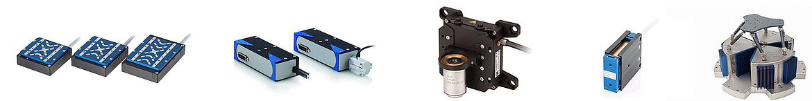
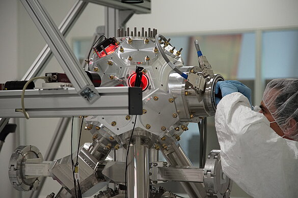
Image: Physik Instrumente (PI)
| 参数 | 压电 | 音圈 |
|---|---|---|
| Travel Range | Unlimited | 1-50 mm |
| 分辨率 | 0.5 nm | 5-50 nm |
| 推力 | 0.5-20 N | 0.1-100 N |
| 保持 | No power | Requires power |
| Heat Generation | 低 | 高 |
| 带宽 | 1-5 kHz | 100 Hz-2 kHz |
| 真空 | 优秀 | 良好 |
| Linearity | N/A | 优秀 |
Operating Principles
Piezoelectric Actuators: Stiffness Devices
A piezoelectric actuator converts electrical field energy directly into mechanical strain. Apply a voltage across a PZT (lead zirconate titanate) ceramic element and it changes dimension, typically by 0.1% to 0.15% of its length. A 10 mm stack actuator produces roughly 10 to 15 micrometers of free stroke. To reach useful travel ranges (tens to hundreds of micrometers), manufacturers bond many thin ceramic layers into a multilayer stack, reducing the required drive voltage to 100 to 150 V while preserving total displacement.
The key physics: piezo actuators are fundamentally stiffness devices. A typical multilayer stack has an axial stiffness of 50 to 500 N/micrometer. They generate force by resisting displacement, not by sustaining current. At full blocking force (zero displacement), a PI P-885.55 PICMA stack produces 850 N from a compact 5 x 5 x 18 mm package, with a stiffness of approximately 50 N/micrometer. The larger P-888.55 reaches 3,400 N blocking force in the same stroke class. The PICA Power series extends this to extremes: blocking forces from 1,200 N (5 micrometer stroke) to 70,000 N (180 micrometer stroke). At free stroke (zero load), force is zero.
For larger displacements, flexure-amplified designs use lever mechanisms to multiply the raw stack displacement. The Cedrat APA range illustrates the stroke-force-bandwidth tradeoff across amplified designs:
| Model | Free Stroke (um) | Blocking Force (N) | Resonance Freq (Hz) | Mass (g) |
|---|---|---|---|---|
| Cedrat APA30uXS | 34 | 3.7 | 4,800 | 1 |
| Cedrat APA60ML | 65 | 3,300 | 2,600 | 450 |
| Cedrat APA300ML | 300 | 540 | 760 | 690 |
| Cedrat APA2000L | 2,000 | 62 | 87 | 1,900 |
The tradeoff is stark: extending stroke by 60x (from 34 to 2,000 micrometers) costs a factor of 55 in resonance frequency and reduces blocking force from 3.7 N to 62 N only because the larger actuator has proportionally more ceramic material. Stiffness drops by roughly three orders of magnitude when mechanical amplification is introduced. For a detailed discussion of this fundamental tradeoff, see load, stroke, and resolution tradeoffs.
Voice Coil Actuators: Force Devices
A voice coil actuator is a single-phase, limited-stroke electromagnetic motor. A coil of wire sits in a permanent magnetic field (typically from NdFeB magnets). Current through the coil produces a Lorentz force proportional to current, magnetic flux density, coil length, and number of turns. The force-stroke relationship is essentially flat across the stroke range, so long as the coil remains within the uniform field region.
The key physics: voice coils are fundamentally force devices. They produce force proportional to current, independent of position (within the linear region). Stiffness is zero; without a position sensor and servo loop, a VCA has no inherent position holding.
The range of available VCA products spans several orders of magnitude in force and stroke:
| Model | Stroke (mm) | Force Constant (N/A) | Continuous Force (N) | Peak Force (N) | Moving Mass (g) | Coil Resistance (ohm) |
|---|---|---|---|---|---|---|
| H2W NCC01-04-001-1X | 3.2 | 0.45 | 0.27 | 0.80 | 1.2 | 1.5 |
| H2W NCC05-11-011-1X | 12.7 | 5.2 | 4.9 | 14.7 | 27 | 3.0 |
| Equipment Solutions VCS-10 | 10 | 4.4 | 6.6 | N/A | 25 | 4.0 |
| H2W NCC10-15-023-1X | 25.4 | 10.2 | 10.2 | 30.7 | 56 | 7.5 |
| H2W NCC10-30-108-1H | 25.4 | 22.0 | 48.1 | 144 | 213 | 4.0 |
| BEI Kimco LA30-48-000A | 25.4 | N/A | 133 | N/A | N/A | N/A |
The motor constant Km (force per square root of power dissipated, units of N/sqrt(W)) is the figure of merit for VCA efficiency. The H2W NCC05-11-011-1X achieves 2.98 N/sqrt(W), the NCC10-15-023-1X reaches 3.8 N/sqrt(W), and the large NCC10-30-108-1H achieves 11.0 N/sqrt(W). The BEI Kimco LA30-48-000A leads at 21.8 N/sqrt(W). Higher Km means less heat for a given force output, which is critical in thermally sensitive applications.
PI's integrated VCA stages provide a ready-to-use alternative: the V-522/V-524/V-528 series offers 5, 10, and 20 mm stroke with 20 nm encoder resolution and 250 mm/s velocity. The A-142 PIglide, with air bearings and a 5 nm encoder, achieves 50 nm minimum incremental motion over 10 mm of travel at speeds up to 200 mm/s.
 PI PIMag V-522/V-528 voice coil linear stages. Direct-drive voice coil with crossed-roller bearings provides zero-cogging motion over 5 to 20 mm of travel at 250 mm/s. Source: PI
Force-Stroke Characteristics
This is the most important distinction and the one most often glossed over in marketing literature.
Piezo actuators have a force-stroke relationship that is linear and bounded by two limits. At zero displacement, blocking force is maximum (often thousands of newtons). At maximum free stroke, force is zero. Every micrometer of displacement costs force, and the rate of that tradeoff is the actuator stiffness. For a PI P-885.55 stack with 50 N/micrometer stiffness and 14 micrometer free stroke, the maximum available force at 7 micrometer displacement is 500 N, exactly half the blocking force.
Voice coil actuators produce constant force at any position within the linear stroke range. An H2W NCC10-15-023-1X rated at 10.2 N continuous delivers 10.2 N whether it is at 0 mm, 5 mm, or 25 mm displacement. The force is limited only by thermal dissipation in the coil.
Practical consequence: if your application needs constant force over the full stroke (active vibration isolation, constant-pressure bonding), a VCA is the natural choice. If your application needs maximum stiffness and force at or near a fixed point (nanopositioning, optical mirror tilt), piezo is superior.
Detailed Force-Displacement Comparison
The following table compares force output at various displacement points for representative actuators in each class. The piezo actuator is a PI P-888.55 stack with 14 micrometer free displacement and 3,400 N blocking force (stiffness approximately 243 N/micrometer). The VCA is an H2W NCC10-15-023-1X with 25.4 mm stroke, 10.2 N/A force constant, and 7.5 ohm coil resistance.
| Displacement (um) | Piezo Available Force (N) | VCA Force at 1 A (N) | VCA Force at 2 A (N) |
|---|---|---|---|
| 0 | 3,400 | 10.2 | 20.4 |
| 1 | 3,157 | 10.2 | 20.4 |
| 3 | 2,671 | 10.2 | 20.4 |
| 5 | 2,186 | 10.2 | 20.4 |
| 7 (half stroke) | 1,700 | 10.2 | 20.4 |
| 10 | 971 | 10.2 | 20.4 |
| 12 | 486 | 10.2 | 20.4 |
| 14 (full stroke) | 0 | 10.2 | 20.4 |
| 100 | N/A (beyond range) | 10.2 | 20.4 |
| 500 | N/A | 10.2 | 20.4 |
| 1,000 (1 mm) | N/A | 10.2 | 20.4 |
The pattern is clear. The piezo actuator dominates in force near its neutral position but delivers zero force at full stroke. The VCA delivers modest but perfectly uniform force across its entire stroke range. For a semiconductor die-bonding tool that must apply exactly 5 N of force at any point within a 200 micrometer travel range, the VCA is the natural fit. For an adaptive optics mirror that must resist 500 N of wind loading while correcting position by 2 micrometers, the piezo is the only realistic option.
Worked Example: Force Budget for a Vertical Positioning Stage
Consider a vertical axis that must support a 200 g payload (1.96 N gravity load) and position it with 10 nm resolution over 100 micrometers of travel.
VCA approach: Use an Equipment Solutions VCS-10, which offers 10 mm stroke, 4.4 N/A force constant, and 4 ohm coil resistance. The gravity compensation current is 1.96 / 4.4 = 0.445 A. At 4 ohm coil resistance, this dissipates 0.445^2 x 4 = 0.79 W continuously. Manageable, but this heat is constant and unavoidable. Adding a counterbalance spring reduces the current but introduces spring rate nonlinearity and potential resonances. Over an 8-hour shift, total thermal energy injected: 0.79 x 28,800 = 22,752 J.
Piezo approach: Use a PI PIHera P-622 stage with 100 micrometer stroke, 0.1 nm resolution, and capacitive sensor feedback. The stage's flexure-guided mechanism has an effective stiffness of approximately 0.5 N/micrometer. The gravity load of 1.96 N displaces the stage by 1.96 / 0.5 = 3.9 micrometers, a fixed offset easily accommodated within the 100 micrometer range. The piezo absorbs the gravity load through its inherent stiffness with zero power consumption. Position control uses voltage modulation, and at static hold, power draw is effectively zero. Over an 8-hour shift, total thermal energy injected: approximately 0.03 J (leakage current only).
The piezo approach wins this scenario decisively on thermal grounds, provided the 100 micrometer stroke is sufficient.
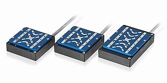
 PI PIFOC fast-focus stages. The compact flexure-guided design delivers sub-nanometer resolution with kilohertz-class bandwidth in a package that mounts directly to microscope objective turrets. Source: PI
Bandwidth and Dynamic Response
Piezoelectric actuators are inherently fast. The mechanical resonance frequency of a bare stack actuator is typically 5 to 60 kHz, depending on mass and stiffness. The PI P-885.55 PICMA stack resonates at approximately 60 kHz unloaded. With a flexure-guided stage and payload, first resonance drops to 0.5 to 5 kHz. The Aerotech QNP series achieves 885 Hz loaded resonance in an XY configuration with 100 to 600 micrometer travel and 0.15 nm resolution. Closed-loop bandwidth (at -3 dB) is usually one-third to one-fifth of the first mechanical resonance, placing practical servo bandwidth at 100 Hz to 1.5 kHz for loaded stages.
Voice coil actuators have lower mechanical resonance because the moving mass (coil or magnet) is supported by soft flexures or air bearings. Typical first resonance is 20 to 200 Hz for a flexure-guided VCA stage. Closed-loop bandwidth is 50 to 500 Hz for most commercial units. High-performance custom VCAs in hard disk drive suspensions have reached 2 to 5 kHz bandwidth, but these are lightweight, short-stroke designs optimized for that specific application. The Equipment Solutions VCS-10 achieves sub-3 ms step response, which corresponds to roughly 100 to 150 Hz bandwidth.
The electrical time constant also matters. Piezo actuators are capacitive loads (typically 0.1 to 10 microfarads for a multilayer stack). The amplifier must charge and discharge this capacitance, which at high frequencies demands significant current. A 1 microfarad piezo driven at 1 kHz with 100 V amplitude requires roughly 0.6 A RMS. At 10 kHz, that rises to 6 A. The amplifier, not the actuator, often becomes the bandwidth bottleneck. Understanding how ultrasonic piezoelectric motors work provides useful context for the resonance phenomena involved.
Voice coils are inductive loads with time constants of 0.1 to 2 ms. At low frequencies, the response is current-limited. At high frequencies, the inductance limits the rate of current change. Most VCA drivers use current-mode amplifiers to push through this limitation.
Bandwidth Comparison Across Stroke Ranges
The bandwidth achievable by each technology varies significantly with the required stroke range. Longer strokes mean larger, heavier stages and lower resonance frequencies for both technologies, but the degradation curve is steeper for piezo actuators because flexure amplification adds mass and compliance.
| Stroke Range | Piezo Closed-Loop BW | VCA Closed-Loop BW | Winner |
|---|---|---|---|
| 5 um (bare stack) | 2 to 10 kHz | N/A (impractical) | Piezo |
| 15 um (stack + flexure) | 500 Hz to 2 kHz | 100 to 300 Hz | Piezo |
| 25 um (PI P-752 LISA) | 400 Hz to 1.5 kHz | 100 to 300 Hz | Piezo |
| 50 um (amplified piezo) | 200 Hz to 800 Hz | 100 to 400 Hz | Piezo (narrower margin) |
| 100 um (nPoint NPXY100Z) | 100 Hz to 500 Hz | 100 to 400 Hz | Comparable |
| 200 um (large amplifier) | 50 Hz to 200 Hz | 80 to 350 Hz | VCA (often) |
| 400 um (PI P-625 PIFOC) | 30 Hz to 120 Hz | 60 to 300 Hz | VCA |
| 500 um | 20 Hz to 100 Hz | 60 to 300 Hz | VCA |
| 1 mm | Impractical for piezo | 50 to 250 Hz | VCA |
| 5 mm (PI V-522) | N/A | 30 to 150 Hz | VCA |
The crossover point is approximately 100 to 200 micrometers of stroke. Below that range, piezo dominates in bandwidth. Above it, the VCA's simpler mechanical design (no lever amplification, lower moving mass per unit stroke) gives it the advantage.
Settling Time Comparison
For step-and-settle applications (semiconductor inspection, pick-and-place), the relevant metric is settling time to a given positional tolerance, not bandwidth per se. The two are related but not identical, because the piezo's high stiffness provides natural damping against external disturbances while the VCA's zero stiffness makes it susceptible to overshoot without careful controller tuning.
| Settling Criterion | Piezo (15 um stroke) | VCA (1 mm stroke) |
|---|---|---|
| To within 1% of final value | 0.3 to 2 ms | 2 to 10 ms |
| To within 0.1% of final value | 1 to 5 ms | 5 to 30 ms |
| To within 10 nm | 0.5 to 3 ms | 3 to 20 ms |
| To within 1 nm | 2 to 10 ms | 10 to 100 ms |
The piezo advantage in settling time is typically a factor of 3 to 10, which is a direct consequence of the higher mechanical resonance frequency and greater inherent stiffness.
Bottom line: piezo wins on raw bandwidth in most configurations, often by a factor of 3 to 10. For applications requiring settling times below 1 ms, piezo is usually the only practical choice. However, at strokes beyond 200 micrometers, the VCA reclaims the bandwidth advantage.
Resolution and Noise Floor
Both technologies can achieve extremely fine resolution, but through different mechanisms.
Piezoelectric actuators have essentially infinite theoretical resolution because ceramic strain is continuous and non-quantized. Practical resolution is limited by the driver electronics (DAC resolution, noise floor) and the mechanical design (flexure hysteresis, sensor noise). Commercial piezo nanopositioning stages routinely achieve 0.1 nm resolution in closed-loop operation with capacitive sensors. The PI PIHera P-620/P-622 series specifies 0.1 nm resolution across travel ranges of 50 to 1,800 micrometers. The nPoint NPXY100Z achieves 0.1 nm resolution over 100 micrometers. Open-loop resolution of 0.01 nm has been demonstrated in laboratory conditions.
Voice coil actuators also have continuous motion with no quantization. Resolution is limited by the position sensor, the current noise in the driver, and external vibration. Commercial VCA stages achieve 1 to 100 nm resolution depending on sensor type (capacitive, interferometric, or encoder). The Equipment Solutions VCS-10 specifies sub-50 nm resolution. The PI A-142 PIglide achieves 50 nm minimum incremental motion with a 5 nm encoder. The best VCA nanopositioning stages approach 0.5 nm resolution with interferometric feedback.
The practical difference is that achieving sub-nanometer resolution with a VCA requires extremely low-noise current sources and excellent shielding from electromagnetic interference, because force is proportional to current and any current noise translates directly into force noise and position error. Piezo actuators are less sensitive to electrical noise because they are voltage-driven and the high stiffness of the ceramic suppresses disturbance-induced motion.
Resolution Sensitivity Analysis
To understand why piezo actuators achieve finer resolution in practice, consider the force noise floor.
VCA noise calculation: An H2W NCC05-11-011-1X voice coil with 5.2 N/A force constant, driven by an amplifier with 1 mA RMS current noise, produces a force noise of 0.0052 N. If the stage has a moving mass of 27 g and a flexure stiffness of 200 N/m:
x_noise = F_noise / k_flexure = 0.0052 / 200 = 26 micrometers (open-loop)
This result is obviously far too large, which is why VCA stages always use closed-loop feedback. The servo loop suppresses this noise within its bandwidth, but beyond the servo bandwidth, the noise passes through. If the servo bandwidth is 200 Hz, noise above 200 Hz causes position error. With typical amplifier noise spectra, the integrated position noise for a VCA stage is 1 to 10 nm RMS.
Piezo noise calculation: For a PI P-752 LISA stage (25 micrometer stroke, 1 nm closed-loop resolution), the actuator stiffness is approximately 100 N/micrometer (100 x 10^6 N/m). A voltage noise of 1 mV RMS on a 100 V drive signal produces a strain noise of:
x_noise = (1 mV / 100 V) x 25 um = 0.25 nm RMS
The piezo's enormous stiffness means that electrical noise and external disturbances translate into vastly smaller position errors. This is the fundamental reason why sub-nanometer positioning is easier to achieve with piezo actuators.
Resolution by Product Class
| Product | Technology | Travel | Specified Resolution | Sensor Type |
|---|---|---|---|---|
| PI P-752 LISA | Piezo | 25 um | 1 nm CL | Capacitive |
| PI PIHera P-622 | Piezo | 250 um | 0.1 nm | Capacitive |
| PI P-625 PIFOC | Piezo | 400 um | 0.1 nm | Capacitive |
| nPoint NPXY100Z | Piezo | 100 um | 0.1 nm | Capacitive |
| Aerotech QNP | Piezo | 100 to 600 um | 0.15 nm | Capacitive |
| Equipment Solutions VCS-10 | VCA | 10 mm | < 50 nm | Encoder |
| PI V-522 | VCA | 5 mm | 20 nm | Encoder |
| PI A-142 PIglide | VCA | 10 mm | 50 nm MIM | Encoder (5 nm) |
The resolution gap is roughly two orders of magnitude (0.1 nm piezo versus 20 to 50 nm VCA) for commercial off-the-shelf stages. Closing this gap with a VCA requires custom ultra-low-noise electronics that typically cost more than the VCA stage itself.
Power Consumption and Thermal Behavior
This is where the comparison becomes stark. The thermal behaviour of each technology has direct consequences for system-level accuracy in precision instruments.
Piezoelectric actuators consume power only when changing position. At static hold, current draw is essentially zero (just leakage current through the ceramic, typically nanoamps). Dynamic power consumption is proportional to frequency, voltage swing, and capacitance: P = pi x f x C x V^2. A 1 microfarad actuator cycling at 100 Hz over 100 V dissipates roughly 3 W. But at a fixed position, heat generation is negligible.
Voice coil actuators consume power whenever holding force. Because a VCA has zero inherent stiffness, holding a position against any external force (including gravity) requires continuous current. Power dissipation is I^2 x R, where R is the coil resistance (typically 1 to 20 ohms). The motor constant Km provides a direct measure of force efficiency: a VCA with Km = 11.0 N/sqrt(W) (H2W NCC10-30-108-1H) dissipates (F/Km)^2 watts for any sustained force F. Holding 10 N requires (10/11)^2 = 0.83 W. Holding 48 N (the rated continuous force) requires (48/11)^2 = 19 W.
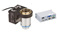
 PI PICMA multilayer stack actuators. At static hold, leakage current is measured in nanoamps and power dissipation is effectively zero, a fundamental thermodynamic advantage over voice coils that require continuous current for any holding force. Source: PI
Thermal Analysis Worked Example: 8-Hour Semiconductor Inspection Shift
Consider a semiconductor inspection station where an actuator must hold a probe tip at a fixed position for 8 hours per shift, with intermittent 10 micrometer repositioning events occurring roughly once per minute.
VCA thermal scenario:
The VCA must hold 3 N against gravity (probe assembly mass of ~300 g). Using an H2W NCC05-11-011-1X (force constant 5.2 N/A, coil resistance 3.0 ohm, Km = 2.98 N/sqrt(W)):
- Holding current: 3 / 5.2 = 0.577 A
- Holding power: 0.577^2 x 3.0 = 1.00 W continuous
- Energy over 8-hour shift: 1.00 x 28,800 = 28,800 J = 28.8 kJ
This 1.0 W is continuous heat injection into the metrology frame. The coil temperature rises according to the thermal resistance of the actuator housing. For a typical 25 mm VCA with thermal resistance of 15 degrees C/W:
- Coil temperature rise: 1.0 x 15 = 15 degrees C above ambient
- If ambient is 22 degrees C, coil reaches 37 degrees C
This temperature rise produces consequences:
- Coil resistance increases by 5.9% (copper TCR of 0.00393/degree C x 15 degrees C), changing the force-to-current relationship
- Thermal expansion of the VCA housing (aluminum, 23 ppm/degree C) produces 23 x 10^-6 x 15 x 25 mm = 8.6 micrometers of dimensional change
- Thermal gradient in the mounting structure causes bimetallic bending, introducing position drift on the order of 0.1 to 1 micrometer per degree C, depending on the structural design
Even with a servo loop correcting position, the thermal drift introduces low-frequency position errors that must be tracked by the sensor and controller. In a high-accuracy metrology application, this thermal perturbation can be the dominant error source.
Piezo thermal scenario:
Use a PI PIHera P-622 with 100 micrometer stroke and capacitive sensor. The piezo actuator holds position at a fixed voltage. Leakage current is approximately 10 nA at 100 V, dissipating 1 microwatt. Over an 8-hour shift, total energy dissipated: 0.029 J. The temperature rise is effectively zero.
During repositioning (once per minute, 10 micrometer step), the piezo capacitance (approximately 1 microfarad) charges from one voltage to another. Energy per transition: 0.5 x C x delta_V^2. For a 10 micrometer step on a 100 micrometer actuator, delta_V is roughly 10 V. Energy: 0.5 x 10^-6 x 10^2 = 0.00005 J. Over 480 transitions per shift: 0.024 J total. Negligible heating.
Net comparison over 8 hours:
| Metric | Piezo (P-622) | VCA (NCC05-11-011-1X) |
|---|---|---|
| Total energy dissipated | 0.05 J | 28,800 J |
| Peak temperature rise | < 0.001 degrees C | 15 degrees C |
| Thermal drift contribution | Negligible | 8.6 um housing, 0.1 to 1 um/C bending |
| Resistance change | N/A | +5.9% (requires recalibration or feedback) |
The thermal advantage is decisive for this application.
Comprehensive Thermal Comparison Table
| Scenario | Piezo Power (W) | VCA Power (W) | Piezo Temp Rise (C) | VCA Temp Rise (C) |
|---|---|---|---|---|
| Static hold, no external load | ~0 | ~0 | ~0 | ~0 |
| Static hold, 1 N gravity load | ~0 | 0.03 to 0.5 | ~0 | 0.5 to 7.5 |
| Static hold, 5 N gravity load | ~0 | 1.0 to 12.5 | ~0 | 15 to 60+ |
| Static hold, 10 N gravity load | ~0 | 4.0 to 50 | ~0 | 60 to 150+ (needs cooling) |
| 10 Hz scanning, 10 um amplitude | 0.03 | 0.1 to 0.5 | ~0 | 1 to 7 |
| 100 Hz scanning, 10 um amplitude | 0.3 | 0.5 to 2.0 | 0.5 | 7 to 30 |
| 1 kHz scanning, 10 um amplitude | 3.0 | 5 to 20 | 5 | 30 to 100+ |
| 100 Hz scanning, 100 um amplitude | 3.0 | 1 to 5 | 5 | 15 to 75 |
At high scanning frequencies, piezo power consumption rises (due to capacitive charging currents), and the gap narrows. At 1 kHz and above, both technologies produce significant heat and may require active cooling. But the static-hold thermal advantage of piezo remains decisive regardless of operating frequency.
Hysteresis and Linearity
Piezoelectric ceramics exhibit significant hysteresis, typically 10% to 15% of full stroke for PZT materials. This means that the displacement at a given voltage depends on the history of applied voltages. In open-loop operation, this introduces positioning errors of 1 to 2 micrometers on a 15 micrometer stroke actuator. Closed-loop control with a position sensor eliminates hysteresis effects but adds cost and complexity. Charge-drive amplifiers can reduce open-loop hysteresis to 1% to 2%, at the expense of more complex driver electronics.
Voice coil actuators are inherently linear within their operating range. Force is proportional to current with excellent fidelity, and the force-position relationship is flat. Non-linearities arise only at the ends of travel (where the coil exits the uniform field region) or at very high forces (where magnetic saturation occurs). In closed-loop operation, VCA linearity is typically 0.01% to 0.1% of full stroke.
For applications demanding high linearity without closed-loop control, the VCA has a clear advantage. For closed-loop applications, both technologies deliver comparable linearity.
Linearity Error Budget Comparison
| Error Source | Piezo (open-loop) | Piezo (closed-loop) | VCA (open-loop) | VCA (closed-loop) |
|---|---|---|---|---|
| Hysteresis | 10% to 15% FS | Eliminated | < 0.1% FS | Eliminated |
| Creep (30 s after step) | 1% to 5% FS | Eliminated | N/A | N/A |
| Thermal drift | 0.01%/degree C | Sensor-limited | 0.05%/degree C | Sensor-limited |
| Amplifier nonlinearity | 0.01% to 0.1% FS | Negligible | 0.01% to 0.1% FS | Negligible |
| Sensor noise floor | N/A | 0.1 to 1 nm | N/A | 1 to 10 nm |
| Total positioning error (15 um range) | 1.5 to 2.5 um | 0.1 to 1 nm | 15 to 30 nm | 1 to 10 nm |
In closed-loop operation, the piezo system achieves roughly 10x better linearity than the VCA system, primarily because the piezo's high stiffness means the position sensor only needs to correct small errors, while the VCA sensor must provide all position information (the actuator has no inherent position reference).
Vacuum and Cleanroom Compatibility
Piezoelectric actuators are well-suited to vacuum environments. The ceramic elements contain no volatiles, outgassing is minimal after a standard bake-out, and there is no heat dissipation from coils to create thermal management challenges in vacuum (where convective cooling is absent). Multilayer stacks are routinely used in ultra-high vacuum (UHV) applications at pressures below 10^-10 mbar. The practical requirements for vacuum and cleanroom operation go well beyond the actuator itself and influence the choice of cables, lubricants, and sensor materials throughout the stage assembly.
 PI vacuum chamber with piezo positioning stages. In vacuum, where convective cooling is absent, the piezo's zero-power hold becomes even more decisive: no heat means no thermal management headaches. Source: PI
Voice coil actuators present challenges in vacuum. The coil dissipates heat continuously, and without convective cooling, thermal management becomes critical. The adhesives in the coil, the wire insulation, and the magnet coatings can outgas. Vacuum-compatible VCAs are available but require special materials, add cost, and typically have reduced force ratings due to thermal derating.
For cleanroom applications, both technologies can be designed for particle-free operation. Piezo flexure stages have no sliding contacts and generate no particles in principle. VCA stages also use flexure guidance and are particle-free. The main cleanroom concern with VCAs is thermal convection currents from the hot coil, which can disturb local air currents in sensitive optical paths.
Vacuum Derating for VCA
The loss of convective cooling in vacuum significantly reduces VCA continuous force ratings. Typical derating factors:
| Pressure Range | Convective Cooling | VCA Continuous Force Derating | Piezo Derating |
|---|---|---|---|
| Atmosphere (1,013 mbar) | Full | 100% (rated) | 100% (rated) |
| Rough vacuum (1 to 10 mbar) | Reduced | 60% to 80% | 100% |
| High vacuum (10^-3 to 10^-6 mbar) | None | 30% to 50% | 100% |
| Ultra-high vacuum (< 10^-9 mbar) | None | 20% to 40% | 100% |
A VCA rated for 10 N continuous in air may only sustain 3 to 5 N in high vacuum without additional thermal management (conductive cooling through the mounting, radiation shields, or Peltier coolers). The piezo actuator operates at full rated performance regardless of pressure, because it generates negligible heat at static hold.
Magnetic Field Emissions
This is often the deciding factor in magnetically sensitive environments and deserves more attention than it typically receives. For a comprehensive treatment of this topic across all precision motor technologies, see the EMI, magnetic fields, and cleanroom compatibility article.
Voice Coil Magnetic Fields
Every voice coil actuator contains permanent magnets, typically sintered NdFeB (neodymium iron boron) with remanence of 1.0 to 1.4 T. These magnets produce stray fields that extend well beyond the actuator housing. The field strength depends on the magnet geometry, the magnetic circuit design, and shielding. Measured stray fields from typical VCAs:
| Distance from VCA Surface | Unshielded Stray Field | Shielded VCA (mu-metal) |
|---|---|---|
| 0 mm (surface) | 5 to 50 mT | 0.5 to 5 mT |
| 10 mm | 1 to 10 mT | 0.1 to 1 mT |
| 50 mm | 0.05 to 0.5 mT | 0.01 to 0.05 mT |
| 100 mm | 0.01 to 0.1 mT | 0.002 to 0.01 mT |
| 500 mm | < 0.005 mT | < 0.001 mT |
For comparison, the Earth's magnetic field is approximately 0.05 mT. A typical VCA produces stray fields exceeding the Earth's field at distances up to 50 mm (unshielded).
In addition to the static field from the permanent magnets, the coil itself generates a time-varying field proportional to the drive current. During dynamic operation, this produces AC magnetic emissions at the actuation frequency and its harmonics. A VCA drawing 1 A through a 25 mm diameter coil produces a field of roughly 0.05 mT at 50 mm, varying at the signal frequency. This AC component can induce voltages in nearby sensor loops and create noise in sensitive measurements.
Piezo Magnetic Fields
Piezoelectric actuators contain no magnetic materials and generate no magnetic fields, static or dynamic. The drive signal is a voltage applied across a dielectric (the ceramic), which produces only an electric field confined almost entirely within the ceramic layers. Stray electric fields at the actuator surface are negligible and attenuate as 1/r^3.
This zero-magnetic-emission property makes piezo actuators the only viable option for:
- Electron microscopy (SEM, TEM): Electron beam deflection sensitivity is approximately 0.3 um per microtesla for a 100 keV beam at 10 mm working distance. A VCA stray field of 0.1 mT at the beam location would produce 30 micrometers of image shift. Unacceptable.
- SQUID magnetometry: SQUID sensors operate at flux noise levels of 10^-15 T/sqrt(Hz). Any ferromagnetic material within 0.5 m degrades performance.
- MRI-compatible devices: The 1.5 to 7 T main field would exert enormous forces on NdFeB magnets in a VCA, making them physically dangerous. Piezo actuators are inherently MRI-compatible.
- Mass spectrometry: Ion beam deflection by stray fields corrupts mass spectra.
- Photoemission electron microscopy (PEEM): Low-energy electrons (1 to 100 eV) are extremely sensitive to stray magnetic fields.
Magnetic Compatibility Summary
| Instrument / Sensitivity Class | Maximum Allowable Stray Field | VCA Compatible? | Piezo Compatible? |
|---|---|---|---|
| General lab instruments | < 0.5 mT at 100 mm | Yes (with care) | Yes |
| Optical interferometry | < 0.05 mT at 50 mm | Marginal (shielded VCA) | Yes |
| Scanning electron microscopy | < 0.001 mT at beam | No (even shielded) | Yes |
| Transmission electron microscopy | < 0.0005 mT at sample | No | Yes |
| SQUID magnetometry | < 10^-9 mT at sensor | No | Yes |
| MRI-compatible systems | Zero ferromagnetics in field | No (safety hazard) | Yes |
| Ion beam / mass spectrometry | < 0.01 mT at beam | No | Yes |
For magnetically sensitive applications, there is no tradeoff to evaluate. Piezo is the only choice.
Fast Steering Mirrors: A Head-to-Head Case Study
Fast steering mirrors (FSMs) provide an excellent comparison ground because both piezo and voice coil versions are commercially available from the same vendor (PI), performing the same function: tip-tilt beam steering with sub-microradian precision.
The Contenders
Piezo FSMs:
- PI S-330: Tip-tilt mirror with +-2, +-5, or +-10 mrad mechanical tilt range. Resonance frequency approximately 330 Hz (loaded). Resolution: 20 nrad. Capacitive sensor feedback. Zero power at hold. No magnetic emissions.
- PI S-335: Extended range, +-35 mrad mechanical tilt. Sub-millisecond step response. Designed for high-dynamic beam steering in laser processing and free-space optical communications.
Voice Coil FSMs:
- PI V-931: Moving-magnet voice coil design. +-4 degrees optical beam deflection (+-2 degrees mechanical), a range roughly 200x larger than the S-330. Resolution: 1 microradian. Continuous duty; can track arbitrary waveforms over the full range.
- Newport FSM-300: +-3 degrees optical beam deflection. 800 Hz bandwidth. Resolution: 2 microradians. Low-inertia moving-mirror design for high-speed scanning.
Performance Comparison
| Parameter | PI S-330 (Piezo) | PI S-335 (Piezo) | PI V-931 (VCA) | Newport FSM-300 (VCA) |
|---|---|---|---|---|
| Mechanical tilt range | +-2 to +-10 mrad | +-35 mrad | +-2 deg | +-1.5 deg |
| Optical beam range | +-4 to +-20 mrad | +-70 mrad | +-4 deg | +-3 deg |
| Angular resolution | 20 nrad | ~50 nrad | 1 urad | 2 urad |
| Bandwidth (-3 dB) | ~100 Hz (loaded) | ~80 Hz | ~60 Hz | 800 Hz |
| Step response | 1 to 3 ms | < 1 ms | 5 to 15 ms | ~1.5 ms |
| Power at hold | ~0 W | ~0 W | 1 to 5 W | 1 to 5 W |
| Magnetic stray field | None | None | Significant | Significant |
| Mirror aperture | 25 to 50 mm | 25 to 50 mm | 25 to 100 mm | 25 mm |
When to Choose Which
Choose piezo FSM (S-330/S-335) when:
- Angular range below +-35 mrad is sufficient (beam pointing correction, wavefront tilt compensation, fiber coupling optimization)
- Sub-microradian resolution is needed (20 nrad is 50x finer than the VCA's 1 microradian)
- The mirror must hold a fixed angle for extended periods without power draw (satellite optical links, interferometer alignment)
- Magnetic emissions would disturb the beam path or adjacent instruments (electron-optical systems, near SQUID sensors)
- Operating in vacuum where continuous coil heating is problematic
Choose voice coil FSM (V-931/FSM-300) when:
- Angular range of degrees is required (large-angle scanning, multi-target pointing, lidar scanning)
- Continuous high-speed scanning is the primary mode (the Newport FSM-300's 800 Hz bandwidth with +-3 degree range is unmatched by any piezo design)
- Resolution of 1 to 2 microradians is sufficient
- Thermal load is acceptable or the system is air-cooled
- Magnetic emissions can be managed or are irrelevant
The resolution difference (20 nrad vs. 1 microradian, a factor of 50) is the most decisive parameter for many optical applications. Adaptive optics, interferometric alignment, and precision beam pointing all benefit from the piezo's finer resolution. Scanning lidar, laser show systems, and wide-angle surveillance all need the VCA's range.
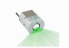 PI fast tip-tilt piezo platform. The dual-axis flexure mechanism is driven by push-pull piezo stacks, achieving 20 nrad resolution with no magnetic components. Voice coil FSMs offer 50x to 100x larger angular range but at 50x coarser resolution. Source: PI
Active Vibration Isolation: Who Wins?
Active vibration isolation is one of the most commercially significant applications for both technologies, and the competitive landscape is illuminating.
Piezo-Based Systems
TMC STACIS III: Uses piezoelectric actuators to provide active vibration isolation from 0.6 to 150 Hz. Achieves greater than 90% vibration attenuation at 2 Hz, an impressive figure for a platform-level system. The piezo actuators operate in a push-pull configuration against a passive pneumatic isolator. At low frequencies (below 5 Hz), where structural vibrations cause the most damage to lithography, microscopy, and interferometry, the STACIS III is the industry standard.
Herzan TS-150: Active from 0.7 to 1,000 Hz, extending the useful isolation bandwidth well into the acoustic range. Uses piezoelectric actuators with inertial sensors. Particularly suited to scanning probe microscopy where acoustic noise (100 to 1,000 Hz) couples into the measurement through building vibrations.
Voice Coil / Electromagnetic Systems
Several active isolation platforms use voice coil or electromagnetic actuators. These systems can operate over larger stroke ranges and provide both vibration isolation and position control. However, the continuous current draw required for active isolation generates heat within the isolation platform, a paradox since thermal stability is often a key requirement for the instruments being isolated.
Passive Comparison Point
Minus K BM-4: A passive negative-stiffness isolator with a natural frequency of 0.5 Hz. Requires zero power, generates zero heat, and achieves excellent low-frequency isolation. However, it provides no active feedback, cannot adapt to changing loads, and has limited high-frequency performance compared to active systems.
Isolation Technology Comparison
| System | Technology | Active Bandwidth | Attenuation at 2 Hz | Power Draw | Thermal Perturbation |
|---|---|---|---|---|---|
| TMC STACIS III | Piezo | 0.6 to 150 Hz | > 90% | Low (piezo, intermittent) | Very low |
| Herzan TS-150 | Piezo | 0.7 to 1,000 Hz | > 85% | Low | Very low |
| Typical VCA active | Voice coil | 1 to 200 Hz | > 80% | Moderate (continuous) | Moderate (2 to 10 W) |
| Minus K BM-4 | Passive | N/A (0.5 Hz natural freq) | > 93% | Zero | Zero |
Analysis
For vibration isolation, piezo actuators have a structural advantage. The isolation actuator must correct for vibrations while holding a payload against gravity. With a piezo system, gravity support comes from the passive spring (pneumatic or mechanical), and the piezo provides only the dynamic correction force. This means the piezo operates near its neutral point with small, dynamic signals, exactly the regime where piezo excels: high stiffness, high bandwidth, zero static power.
A voice coil isolation actuator, by contrast, must either carry part of the gravity load (continuous current, continuous heat) or rely entirely on a passive spring for static support. If the passive spring is imperfect, the VCA must compensate, generating heat on the isolation table where thermal stability matters most.
The TMC STACIS III's dominance in semiconductor fab vibration isolation is not accidental. The combination of piezo actuators and pneumatic springs delivers the required low-frequency performance (< 2 Hz) with minimal thermal disturbance to the lithography tools sitting on the platform. For fab environments where temperature stability of +-0.01 degrees C is required, the piezo approach is the only viable active solution.
Cost Comparison
The cost comparison depends heavily on the performance tier and stroke range. Below is a detailed breakdown for complete, ready-to-use positioning stages (actuator, driver, sensor, and controller included).
| Performance Tier | Stroke | Piezo System Cost | VCA System Cost | Notes |
|---|---|---|---|---|
| Basic open-loop | 15 um | $300 to $800 | N/A | VCA impractical without feedback |
| Closed-loop, 100 nm res. | 15 um | $1,500 to $3,000 | $1,000 to $2,500 | Piezo simpler; VCA needs good sensor |
| Closed-loop, 10 nm res. | 15 um | $2,500 to $5,000 | $2,000 to $4,000 | Comparable cost, piezo better performance |
| Closed-loop, 1 nm res. | 15 um | $4,000 to $8,000 | $5,000 to $12,000 | VCA needs ultra-low-noise driver |
| Closed-loop, 100 nm res. | 100 um | $3,000 to $6,000 | $1,500 to $3,500 | Piezo needs amplification; VCA natural |
| Closed-loop, 100 nm res. | 500 um | $6,000 to $15,000 | $2,000 to $5,000 | Piezo at stroke limit; VCA clearly cheaper |
| Closed-loop, 100 nm res. | 1 mm | Impractical (single stage) | $2,500 to $6,000 | VCA is the only option |
| Closed-loop, 100 nm res. | 5 mm | N/A | $3,000 to $8,000 | VCA only |
| Vacuum compat., 10 nm res. | 15 um | $5,000 to $10,000 | $8,000 to $20,000 | VCA vacuum derating + thermal mgmt |
| Vacuum compat., 10 nm res. | 100 um | $6,000 to $12,000 | $6,000 to $15,000 | Comparable, piezo simpler in vacuum |
Key cost observations:
- At short strokes (below 50 micrometers), piezo is often cheaper for a given resolution because the driver electronics are simpler and no elaborate thermal management is needed.
- At longer strokes (above 200 micrometers), VCA becomes cheaper because piezo actuators need flexure amplification, which adds mechanical complexity and cost.
- For vacuum applications, piezo systems are almost always cheaper at equivalent performance because VCA vacuum compatibility requires expensive thermal solutions.
- The amplifier cost is often the hidden driver. A high-voltage piezo amplifier capable of driving 1 microfarad at 1 kHz costs $500 to $2,000. A low-noise current amplifier for a VCA costs $300 to $1,500. At sub-nanometer resolution, the VCA amplifier cost rises sharply because current noise requirements tighten.
Application Decision Scenarios
Scenario 1: Autofocus for a Microscope Objective
Requirements: 200 micrometer travel, 50 nm resolution, 100 Hz bandwidth, atmospheric pressure, continuous scanning during image acquisition, vertical axis (gravity load of 150 g objective).
Analysis: The 200 micrometer stroke is at the upper limit for amplified piezo actuators and well within VCA range. The 50 nm resolution is achievable by both technologies. The continuous scanning duty cycle means the VCA's power consumption is comparable to the piezo's capacitive losses. The gravity load of 1.47 N creates a continuous thermal load for the VCA (roughly 0.15 W, manageable).
Recommendation: VCA. The stroke range favors it, the resolution is easily achievable, and the continuous scanning duty cycle means the piezo's static-hold advantage is unused. A PI V-522 with 5 mm stroke and 20 nm encoder provides an elegant solution with massive headroom. Cost: approximately $2,000 to $4,000 complete.
If the requirement changes to 20 micrometer travel and 500 Hz bandwidth (e.g., for confocal Z-scanning), the answer flips to piezo.
Scenario 2: Active Mirror Alignment in a Laser Cavity
Requirements: 5 micrometer travel, 0.5 nm resolution, 1 kHz bandwidth, hold for hours between adjustments, vibration immunity from adjacent equipment, low magnetic emission (nearby magnetometer).
Analysis: The short stroke (5 micrometers) and high bandwidth (1 kHz) strongly favor piezo. The 0.5 nm resolution is routine for piezo with a capacitive sensor but would require an expensive ultra-low-noise current driver for a VCA. The hours-long hold time creates a significant thermal penalty for the VCA. The magnetic sensitivity requirement eliminates the VCA entirely (NdFeB magnets produce stray fields of 0.1 to 10 mT at the actuator surface).
Recommendation: Piezo, definitively. A PI P-752 LISA (25 micrometer stroke, 1 nm resolution) or a similar closed-loop piezo stack with capacitive sensor achieves all requirements with margin. Cost: approximately $3,000 to $6,000 complete.
Scenario 3: Vibration Isolation for a Scanning Electron Microscope
Requirements: Active isolation from 0.5 to 200 Hz, support 500 kg instrument, temperature stability of +-0.05 degrees C at the sample, zero magnetic emissions within 1 m of the electron column.
Analysis: The magnetic requirement immediately eliminates voice coil isolators. Even well-shielded VCA systems produce stray fields exceeding 0.001 mT at 500 mm, which would deflect the SEM electron beam. The temperature stability requirement penalizes continuous heat sources. The low-frequency requirement (0.5 Hz) demands active isolation; passive isolators alone cannot achieve 90% attenuation at 1 to 2 Hz without impractically soft springs.
Recommendation: Piezo active isolation (TMC STACIS III or equivalent). The piezo-pneumatic combination provides the bandwidth, the thermal neutrality, and the zero magnetic emissions required. Cost: $30,000 to $60,000 for a complete platform, but this is standard for SEM-grade isolation.
Scenario 4: Pick-and-Place Die Bonding
Requirements: 500 micrometer Z-travel, 1 micrometer resolution, 50 Hz bandwidth, vertical axis, 100 g tool head, 200 ms cycle time, clean room Class 100.
Analysis: The 500 micrometer stroke pushes the boundary of amplified piezo actuators. The 1 micrometer resolution and 50 Hz bandwidth are within comfortable range for both technologies. The 200 ms cycle time is not demanding. The vertical axis creates a gravity load of 0.98 N. In a clean room, particle generation and thermal convection currents matter.
Recommendation: VCA. The stroke is more naturally suited to voice coil. The moderate resolution means a 20 nm encoder is more than sufficient. The 0.98 N gravity load dissipates only 0.06 W (using a Km = 4 N/sqrt(W) VCA), which is thermally acceptable even in a clean room. A Celera Motion Juke Flat series actuator with appropriate guidance could be a compact solution. Cost: approximately $2,000 to $5,000.
If the stroke were 100 micrometers and the cycle time were 10 ms, piezo would be the better choice.
Scenario 5: Fiber Alignment for Photonic Chip Coupling
Requirements: 3-axis positioning, 30 micrometer travel per axis, 1 nm resolution, 200 Hz bandwidth, hold alignment indefinitely once optimized, vacuum-compatible (1 x 10^-6 mbar packaging environment), zero magnetic fields near the photonic chip.
Analysis: Every requirement favors piezo. The 30 micrometer stroke is well within stack + flexure range. The 1 nm resolution is standard for capacitive-sensor piezo stages. The 200 Hz bandwidth is easily achieved. The indefinite hold with zero power is a piezo strength. Vacuum operation requires no derating. Zero magnetic emissions protect the photonic chip from Faraday rotation or magneto-optic effects.
Recommendation: Piezo, all three axes. An nPoint NPXY100Z (XY) plus a single-axis piezo Z stage provides 100 micrometer travel in XY and appropriate Z travel, all with 0.1 nm resolution. Or a PI P-620/P-622 PIHera stage configuration. In vacuum at 10^-6 mbar, the piezo system operates at full rated performance with no thermal derating. A VCA in this environment would need extensive thermal management and magnetic shielding, adding cost, complexity, and risk. Cost: approximately $10,000 to $20,000 for three-axis system.
Scenario 6: Constant-Force Tactile Probing on a CMM
Requirements: 2 mm Z-travel, 0.1 micrometer resolution, constant contact force of 0.05 N over full travel, low bandwidth (10 Hz), atmospheric operation.
Analysis: The constant-force requirement over 2 mm travel is the deciding factor. A piezo actuator would need to vary its voltage continuously to maintain constant force as displacement changes, effectively fighting its own stiffness characteristic. A VCA naturally provides constant force proportional to current, regardless of position. The 2 mm stroke is well beyond single-stage piezo range. The resolution is modest for either technology.
Recommendation: VCA. The constant-force requirement and 2 mm stroke make this a clear VCA application. An H2W NCC05-11-011-1X (12.7 mm stroke, 4.9 N continuous) is more than sufficient. At 0.05 N holding force and Km = 2.98 N/sqrt(W), power dissipation is (0.05/2.98)^2 = 0.28 mW. Negligible thermal impact. Cost: approximately $1,500 to $3,000.
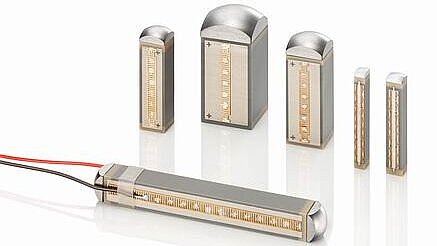
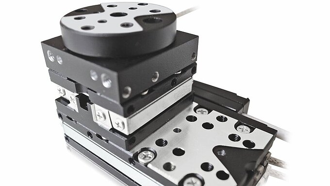 Multi-stage coarse/fine architecture: a long-travel coarse stage (bottom) carries a compact fine-positioning stage (top). This approach combines the VCA's stroke advantage with the piezo's resolution advantage, achieving performance no single technology can deliver alone. Source: PI
Hybrid Coarse/Fine Architectures
Increasingly, system designers combine both technologies in a single positioning system, as explored in the load-stroke-resolution tradeoffs analysis. The most common hybrid architecture uses a VCA for coarse positioning over a long stroke (1 to 25 mm) with a piezo stage for fine positioning over a short stroke (10 to 100 micrometers). The VCA handles the long-range slew and the piezo handles the final settling and precision hold.
The ASML TWINSCAN Dual-Stage: The Definitive Example
The most sophisticated hybrid coarse/fine system in production is the ASML TWINSCAN lithography wafer stage. Understanding this architecture illuminates the engineering logic of combining the two technologies.
Coarse stage (voice coil): The TWINSCAN wafer table rides on a magnetically levitated platform driven by Lorentz-force (voice coil principle) motors. Six degrees of freedom are actively controlled. The stage achieves 7G peak acceleration, enabling the rapid scanning and stepping motions needed for lithography at throughputs exceeding 300 wafers per hour. The voice coil motors provide the long stroke (hundreds of millimeters in X and Y) and high acceleration, but their settling accuracy is limited to the order of 10 to 100 nm by servo bandwidth, amplifier noise, and structural dynamics.
Position sensing: The TWINSCAN uses an interferometric measurement system with 60 pm sensor accuracy (0.06 nm). This extraordinary measurement resolution reveals the limitations of the voice coil stage's positioning performance: at the scale of angstroms, the voice coil servo loop cannot track every disturbance.
Fine stage (piezo, research): Research at TU Eindhoven has investigated adding a piezoelectric fine positioning stage to the TWINSCAN architecture. The goal: reduce settle time to below 10 ms and achieve positional stability of less than 5 nm during exposure, even as the coarse stage introduces nanometer-level vibrations from its servo corrections. The piezo fine stage, mounted between the wafer chuck and the coarse stage, operates over a 10 to 50 micrometer stroke range with multi-kHz bandwidth. Its high stiffness (tens of N/micrometer) provides passive vibration rejection of high-frequency disturbances that the voice coil servo cannot follow.
This dual-stage concept encapsulates the fundamental complementarity of the two technologies. The VCA provides range and acceleration. The piezo provides bandwidth and stiffness. Neither technology alone can meet the combined requirements of the most demanding positioning applications.
Other Hybrid Architectures
The ASML example is the extreme case, but simpler hybrid systems are common:
Microscopy autofocus: A PI V-524 voice coil stage (10 mm stroke, 20 nm encoder, 250 mm/s) provides coarse Z-positioning, while a PI P-625 PIFOC (400 micrometer stroke, 0.1 nm resolution) provides fine focus with high bandwidth.
Scanning probe microscopy: A VCA XY stage provides 5 to 25 mm of coarse positioning for sample navigation, while a piezo XY scanner (nPoint NPXY100Z, 100 micrometer travel, 0.1 nm resolution) provides the scan field for atomic-resolution imaging.
Satellite optical communications: A voice coil FSM (PI V-931, +-4 degrees) provides acquisition and coarse tracking of the remote terminal, while a piezo FSM (PI S-330, +-10 mrad, 20 nrad resolution) provides fine pointing to maintain the optical link.
Hybrid Architecture Performance Summary
| Architecture | Coarse Stage | Fine Stage | Total Stroke | System Resolution | System BW | Typical Cost |
|---|---|---|---|---|---|---|
| VCA + Piezo stack | VCA, 5 mm | Piezo, 15 um | 5.015 mm | 0.1 nm | 1 kHz (fine) | $8,000 to $20,000 |
| VCA + Amplified piezo | VCA, 25 mm | Piezo, 100 um | 25.1 mm | 1 nm | 500 Hz (fine) | $10,000 to $30,000 |
| VCA isolation + Piezo nano | VCA, 2 mm | Piezo, 50 um | N/A (isolation) | 0.1 nm | 200 Hz (iso), 1 kHz (nano) | $15,000 to $40,000 |
| ASML-class dual stage | VCA maglev, 300 mm | Piezo, 50 um | 300 mm | < 1 nm | Multi-kHz (fine) | Custom (millions) |
The tradeoff with hybrid systems is complexity: two actuators, two drivers, two sensors, and a controller that must coordinate both loops without introducing instabilities. Typical hybrid system costs run 1.5x to 2.5x the cost of a single-technology solution, but the performance gains often justify the investment in applications where the requirements genuinely span both technology domains.
Quantitative Comparison Summary
| Parameter | Piezo (flexure stage) | Voice Coil (flexure stage) |
|---|---|---|
| Typical stroke | 5 to 500 um | 0.1 to 50 mm |
| Resolution (closed-loop) | 0.1 to 1 nm | 1 to 100 nm |
| Bandwidth (-3 dB) | 100 Hz to 1.5 kHz | 50 to 500 Hz |
| Settling to 0.1% | 1 to 5 ms | 5 to 30 ms |
| Continuous force | 10 to 1,000 N (position-dependent) | 1 to 50 N (constant) |
| Stiffness | 10 to 500 N/um | ~0 (open-loop) |
| Static power at hold | ~0 W | 1 to 50 W (load-dependent) |
| Dynamic power (100 Hz, 10 um) | 0.3 W | 0.5 to 2 W |
| Hysteresis (open-loop) | 10% to 15% | < 1% |
| Linearity (closed-loop) | 0.001% to 0.01% | 0.01% to 0.1% |
| Vacuum compatibility | Excellent (no derating) | Moderate (30% to 50% force derating) |
| Magnetic emission | None | Significant (0.1 to 10 mT at surface) |
| Operating temp range | -40 to +150 deg C | -20 to +80 deg C (coil limited) |
| Lifetime | Effectively unlimited (no wear) | Effectively unlimited (no wear) |
| Typical unit cost | $500 to $5,000 | $200 to $3,000 |
| Typical system cost | $1,500 to $12,000 | $1,000 to $8,000 |
Decision Framework Summary
The full technology selection framework provides a systematic methodology for choosing between all precision motion technologies. For the specific piezo vs. voice coil decision, the following flowchart captures the key branch points. This is also informed by the broader comparison in piezo vs. servo and piezo vs. stepper, which map adjacent technology boundaries.
Step 1: Stroke
Is the required stroke greater than 500 micrometers?
- Yes: Voice coil is the primary candidate. Piezo can participate only as a fine stage in a hybrid architecture.
- No: Continue to Step 2.
Step 2: Resolution
Is the required resolution below 1 nm?
- Yes: Piezo with capacitive sensor is the primary candidate. VCA cannot reliably achieve sub-nanometer resolution without extraordinary (and expensive) measures.
- No: Continue to Step 3.
Step 3: Bandwidth
Is the required closed-loop bandwidth above 500 Hz?
- Yes: Piezo is strongly favored. Few VCA stages achieve this bandwidth, and those that do are specialized and expensive.
- No: Continue to Step 4.
Step 4: Duty Cycle
Does the actuator spend more than 50% of its operating time holding a fixed position under load?
- Yes: Piezo is strongly favored for its zero-power hold and absence of thermal injection.
- No: Continue to Step 5.
Step 5: Magnetic Sensitivity
Is the system located near magnetically sensitive instruments (electron beams, SQUID sensors, MRI)?
- Yes: Piezo is required. VCA is disqualified.
- No: Continue to Step 6.
Step 6: Vacuum
Will the system operate in vacuum (below 10 mbar)?
- Yes: Piezo is strongly favored. VCA requires thermal derating and specialized thermal management that adds cost and complexity.
- No: Continue to Step 7.
Step 7: Force Profile
Does the application require constant force over the full stroke (gravity compensation, constant-pressure contact, active damping)?
- Yes: VCA is the natural choice. Its flat force-stroke characteristic is ideal.
- No: Continue to Step 8.
Step 8: Cost Sensitivity
Is the budget constrained and the resolution requirement above 10 nm?
- Yes, and stroke is above 100 micrometers: VCA is typically cheaper.
- Yes, and stroke is below 100 micrometers: Piezo is typically cheaper (open-loop piezo is the least expensive option if hysteresis is acceptable).
- No: Choose based on secondary performance factors.
Quick Reference Decision Table
| Primary Requirement | Recommended Technology | Confidence |
|---|---|---|
| Stroke > 500 um | Voice Coil | High |
| Stroke < 50 um | Piezo | High |
| Resolution < 1 nm | Piezo | Very high |
| Bandwidth > 500 Hz | Piezo | High |
| Static hold under load | Piezo | Very high |
| Constant force over stroke | Voice Coil | Very high |
| Vacuum operation | Piezo | High |
| Zero magnetic emission | Piezo | Absolute |
| Stroke 100 to 500 um, moderate resolution | Either (evaluate full tradeoffs) | Medium |
| Continuous scanning, mm stroke | Voice Coil | High |
| Lowest cost, > 10 nm resolution | Depends on stroke (see table) | Medium |
The Honest Bottom Line
There is no universal answer, but there is almost always a clear winner for a specific set of requirements. The technologies are genuinely complementary: piezo actuators excel at short-stroke, high-stiffness, high-bandwidth, thermally silent, magnetically clean positioning. Voice coil actuators excel at longer strokes, constant-force applications, linear open-loop behavior, and cost-effective moderate-resolution systems.
Define your stroke, resolution, bandwidth, duty cycle, thermal budget, vacuum requirements, and magnetic constraints precisely. Run through the decision framework above. In the vast majority of cases, the answer will be unambiguous. And for the remaining cases, where the requirements genuinely span both domains, that is when you build a hybrid system and let each technology do what it does best.